Download
1 / 26
270 likes | 274 Views
Learn about the input-output architecture, types of I/O devices, and the disk access time in CSE 378. Explore how the CPU, memory, and I/O devices are connected and the improvements in disk technology.

E N D
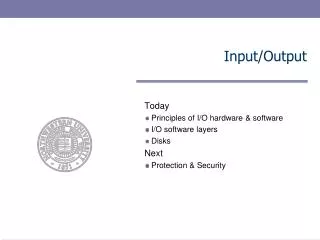
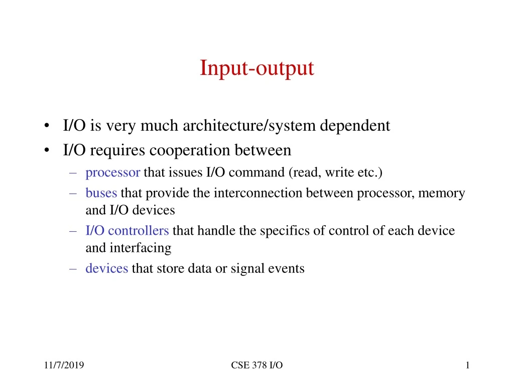
Input-output • I/O is very much architecture/system dependent • I/O requires cooperation between • processor that issues I/O command (read, write etc.) • buses that provide the interconnection between processor, memory and I/O devices • I/O controllers that handle the specifics of control of each device and interfacing • devices that store data or signal events CSE 378 I/O
Basic (simplified) I/O architecture CPU Cache Bus M.Cont. D.Cont. N.Interface Main memory Disks Network CSE 378 I/O
Types of I/O devices • Input devices • keyboard, mouse • Output devices • screen, line printer • Devices for both input and output • disks, network interfaces CSE 378 I/O
An important I/O device: the disk track platters sector Cylinder Read-write heads Disk surface CSE 378 I/O
Secondary memory (disks) • Physical characteristics • Platters (1 to 20) with diameters from 1.3 to 8 inches (recording on both sides) • Tracks (1,000 to 10,000) • Cylinders (all the tracks in the same position in the platters) • Sectors (e.g., 128-256 sectors/track with gaps and info related to sectors between them; typical sector 512 bytes) • Current trend: constant bit density, i.e., more info (sectors) on outer tracks CSE 378 I/O
Example: IBM Ultrastar 146Z10 • Disk for server • 146 GB • 8 MB cache • 10,000 RPM • 3 ms average latency • Up to 6 platters; Up to 12 heads • Average seek latency 4.7 ms • Sustained transfer rate 33-66 MB/s CSE 378 I/O
Disk access time • Arm(s) with a reading/writing head • Four components in an access: • Seek time (to move the arm on the right cylinder). From 0 (if arm already positioned) to a maximum of 15-20 ms. Not a linear function. Smaller disks have smaller seek times. Ultrastar example: Average seek time = 4.7 ms; • My guess: track to track 0.5 ms; longest (inmost strack to outmost track) 8 ms • Rotation time (on the average 1/2 rotation). At 3600 RPM, 8.3 ms. Current disks are 3600 or 5400 or 7200 or even 10,000 RPM (e.g., the Ultrastar, hence average is 3 ms) CSE 378 I/O
Disk access time (ct’d) • Transfer time depends on rotation time, amount to transfer (minimal size a sector), recording density, disk/memory connection. Today, transfer time occurs at 6 to 66 MB/second • Disk controller time. Overhead to perform an access (of the order of 1 ms) • But … many disk controllers have a cache that contains recently accessed sectors. If the I/O requests hits in the cache, the only components of access time are disk controller time and transfer time (which is then of the order of 40 MB/sec). Cache is also used to prefetch on read. CSE 378 I/O
Improvements in disks • Capacity (via density). Same growth rate as DRAMs • Price decrease has followed (today $2-$10/GB?) • Access times have decreased but not enormously • Higher density -> smaller drives -> smaller seek time • RPM has increased slightly 3600 upto 10,000 (rarely) • Transfer time has improved • CPU speed - DRAM access is one “memory wall” • DRAM access time - Disk access time is a “memory gap” • Technologies to fill the gap have not succeeded (currently the most promising is more DRAM backed up by batteries) CSE 378 I/O
Connecting CPU, Memory and I/O CPU-Memory bus Cache Bus adapter Main memory CPU I/O bus I/O contr. I/O contr. I/O contr. disk Graphics Network CSE 378 I/O
Buses • Simplest interconnect • Low cost: set of shared wires • Easy to add devices (although variety of devices might make the design more complex or less efficient -- longer bus and more electrical load; hence the distinction between I/O buses and CPU/memory buses) • But bus is a single shared resource so can get saturated (both physically because of electrical load, and performance-wise because of contention to access it ) • Key parameters: • Width(number of lines:data, addresses, control) • Speed (limited by length and electrical load) CSE 378 I/O
Memory and I/O buses • CPU/memory bus: tailored to the particular CPU • Fast (separate address and data lines; of course separate control lines) • Often short and hence synchronous (governed by a clock) • Wide (64-128 and even 256 bits) • Expensive • I/O bus: follows some standard so many types of devices can be hooked on to it • Asynchronous (hand-shaking protocol) • Narrower CSE 378 I/O
Bus transactions • Consists of arbitration and commands • Arbitration: who is getting control of the bus • Commands: type of transaction (read, write, ack, etc…) • Read, Write, Atomic Read-Modify-Write (atomic swap) • Read: send address and data is returned • Write: send address and data • Read-Modify-write : keep bus during the whole transaction. Used for synchronization between processes CSE 378 I/O
Bus arbitration • Arbitration: who gets the bus if several requests occur at the same time • Only one master (processor): centralized arbitration • Multiple masters (most common case): centralizedarbitration (FIFO, daisy-chain, round-robin, combination of those) vs. decentralized arbitration (each device knows its own priority) • Communication protocol between master and slave • Synchronous (for short buses - no clock skew - i.e. CPU/memory) • Asynchronous (hand-shaking finite-state machine; easier to accommodate many devices) CSE 378 I/O
Hand-shaking protocol • Example : Master (CPU) requests data from Slave (Mem) 1. Master transmits a read request (control lines) and address (address/data lines) 2. Slave recognizes the request. Grabs the address and raises the Ack control line. 3. Master sees the Ack line high. Releases the request and data lines 4. Slave sees the Read request low. Releases the Ack line 5. Slave is ready to transmit data. Places data on data lines and raises Data ready (control line) 6. Master sees Data ready high. Grabs data and raises Ack 7. Slave sees Ack high. Releases data line and Data Ready 8. Master sees Data Ready low. Releases Ack. Transaction is finished CSE 378 I/O
Split-transaction buses • Split a read transaction into • Send address (CPU is master) • Send data (Memory is master) • In between these two transactions (memory access time) the bus is freed • Requires “tagging” the transaction • Can even have more concurrency by having different transactions using the data and address lines concurrently • Useful for multiprocessor systems and for I/O CSE 378 I/O
I/O Hardware-software interface • I/O is best left to the O.S. (for protection and scheduling in particular) • O.S. provides routines that handles devices (or controllers) • But since O.S. is a program, there must be instructions to generate I/O commands • CPU must be able to: • tell a device what it wants done (e.g., read, write, etc.) • start the operation (or tell the device controller to start it) • find out when the operation is completed (with or without error) • No unique way to do all this. Depends on ISA and I/O architecture CSE 378 I/O
I/O operations • Specific I/O instructions • I/O instruction specifies both the device number and a command (or an address where the I/O device can find a series of commands) Example: Intel x86 (IN and OUT between EAX register and an I/O port whose address is either an immediate or in the DX register) • Memory-mapped I/O • Portions of address space devoted to I/O devices (read/write to these addresses transfer data or are used to control I/O devices) • Memory ignores these addresses • In both cases, only the O.S. can execute I/O operations or read/write data to memory-mapped locations CSE 378 I/O
I/O termination • Two techniques to know when an I/O operation terminates • Polling • Interrupts • Polling • CPU repeatedly checks whether a device has completed • Used for “slow” devices such as the mouse (30 times a second) • Interrupts • When the I/O completes it generates an (I/O) interrupt CSE 378 I/O
I/O interrupts • An interrupt is like an exception • Exception created by the program (page fault, divide by zero etc.) • Interrupts occur as a consequence of external stimuli (I/O, power failure etc.) • Presence of an interrupt checked on every cycle • Upon an interrupt, O.S. takes over (context-switch) • Two basic schemes to handle the interrupt • Vectoredinterrupts: the O.S. is told (by the hardware) where to handle the interrupt • Use of a cause register. The O.S. has to examine the contents of that register to transfer to the appropriate handler CSE 378 I/O
Data transfer to/from I/O device • Can be done either by • Using the CPU to transfer data from (to) the device to (from memory. • Can be done either via polling (programmed I/O operation) or interrupt • Slow operation • Using DMA (direct-memory address) CSE 378 I/O
DMA • Having long blocks of I/O go through the processor via load-store is totally inefficient • DMA (direct memory address) controller: • specialized “processor” for transfer of blocks between memory and I/O devices w/o intervention from CPU (except at beg. and end) • Has registers set up by CPU for beginning memory address and count • DMA device interrupts CPU at end of transfer • DMA device is a master for the bus • More complex DMA devices become I/O processors or channels controllers (with their own stored programs) CSE 378 I/O
DMA and virtual memory • What if the block to transfer is greater than 1 page • Address translation registers within the DMA device • What if the O.S. replaces a page where transfer is taking place • Pages are “pinned” (locked) during transfer CSE 378 I/O
I/O and caches • Recall previous discussion • Write-back caches: • on output, the O.S. flushes the cache before the page is written out • on input, blocks in the cache are invalidated • Write-through caches • on output, no problem since cache and memory are consistent • on input, as in write-back • Other possibilities • Use a “snoopy” protocol (cache controller listen to transactions on the memory bus and reacts accordingly) • Have the I/O go through the cache (but not efficient) CSE 378 I/O
Disk arrays • Reliability: is anything broken? • Availability: is the system still usable? • Availability can be improved by adding more hardware (e.g.,ECC, disk arrays) that provides some redundancy • In the case of I/O, simplest redundant system is mirroring: write each data on two disks. • Cost: double the amount of hardware • Performance: no improvement (in fact might be worse for writes since has to wait for the longest of the two to complete) CSE 378 I/O
RAIDs • Concept of striping: data written consecutively on N disks • Performance wise: no improvement in latency but improvement in throughput (parallelism) • But now probability of failure is greater • So add disks (redundant arrays of inexpensive disks) • Mirroring = RAID1 • RAID 5: interleave the parity sectors on the disks CSE 378 I/O