Download
1 / 42
440 likes | 919 Views
Force and Motion Part II Circular Dynamics. February 15, 2006. Schedule. Wednesday A few problems from Chapter 5 (very few) … probably only one…. if that. Force and Motion while spinning around in a circle. Friday More running around in a circle Monday

E N D
Force and Motion Part IICircular Dynamics February 15, 2006
Schedule • Wednesday • A few problems from Chapter 5 (very few) … probably only one…. if that. • Force and Motion while spinning around in a circle. • Friday • More running around in a circle • Monday • Quiz on end of chapter 5 and what we cover this week in chapter 6. • Review of problems.
Screwed this up a bit! Everything that we did was ok but I had the frictional force going in the wrong direction. SHAME ON ME!
Problem What horizontal force must be applied to the cart shown in Figure P5.61 in order that the blocks remain stationary relative to the cart? Assume all surfaces, wheels, and pulley are frictionless. (Hint: Note that the force exerted by the string accelerates m1.)
Another Problem An object of mass M is held in place by an applied force F and a pulley system as shown in Figure P5.55. The pulleys are massless and frictionless. Find (a) the tension in each section of rope, T1, T2, T3, T4, and T5 and (b) the magnitude of F. Suggestion: Draw a free-body diagram for each pulley.
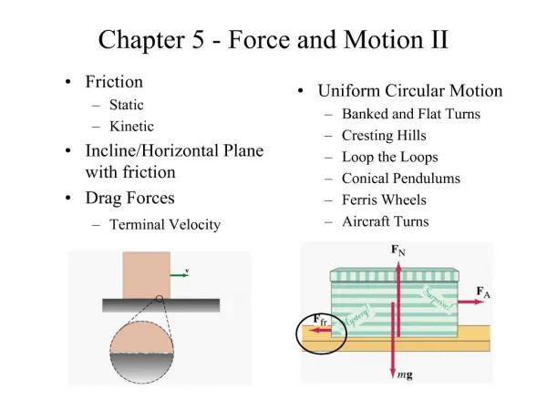
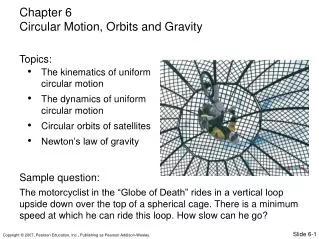
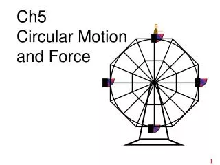
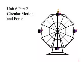
Chapter 6 Circular Motion and Other Applications of Newton’s Laws
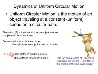
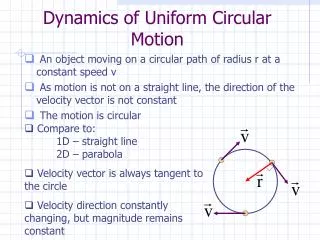
Uniform Circular Motion • A force, Fr , is directed toward the center of the circle • This force is associated with an acceleration, ac • Applying Newton’s Second Law along the radial direction gives
Uniform Circular Motion, cont • A force causing a centripetal acceleration acts toward the center of the circle • It causes a change in the direction of the velocity vector • If the force vanishes, the object would move in a straight-line path tangent to the circle CENTRIPETAL FORCE
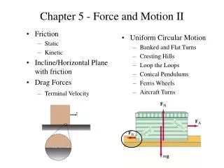
Conical Pendulum • The object is in equilibrium in the vertical direction and undergoes uniform circular motion in the horizontal direction • v is independent of m
Horizontal (Flat) Curve • The force of static friction supplies the centripetal force • The maximum speed at which the car can negotiate the curve is • Note, this does not depend on the mass of the car
Banked Curve • These are designed with friction equaling zero • There is a component of the normal force that supplies the centripetal force
Loop-the-Loop • This is an example of a vertical circle • At the bottom of the loop (b), the upward force experienced by the object is greater than its weight
Loop-the-Loop, Part 2 • At the top of the circle (c), the force exerted on the object is less than its weight
Non-Uniform Circular Motion • The acceleration and force have tangential components • Fr produces the centripetal acceleration • Ft produces the tangential acceleration • SF = SFr+SFt
Vertical Circle with Non-Uniform Speed • The gravitational force exerts a tangential force on the object • Look at the components of Fg • The tension at any point can be found
Top and Bottom of Circle • The tension at the bottom is a maximum • The tension at the top is a minimum • If Ttop = 0, then
Motion in Accelerated Frames • A fictitious force results from an accelerated frame of reference • A fictitious force appears to act on an object in the same way as a real force, but you cannot identify a second object for the fictitious force
“Centrifugal” Force • From the frame of the passenger (b), a force appears to push her toward the door • From the frame of the Earth, the car applies a leftward force on the passenger • The outward force is often called a centrifugal force • It is a fictitious force due to the acceleration associated with the car’s change in direction
“Coriolis Force” • This is an apparent force caused by changing the radial position of an object in a rotating coordinate system • The result of the rotation is the curved path of the ball
Fictitious Forces, examples • Although fictitious forces are not real forces, they can have real effects • Examples: • Objects in the car do slide • You feel pushed to the outside of a rotating platform • The Coriolis force is responsible for the rotation of weather systems and ocean currents
Fictitious Forces in Linear Systems • The inertial observer (a) sees • The noninertial observer (b) sees
Fictitious Forces in a Rotating System • According to the inertial observer (a), the tension is the centripetal force • The noninertial observer (b) sees
Motion with Resistive Forces • Motion can be through a medium • Either a liquid or a gas • The medium exerts a resistive force, R, on an object moving through the medium • The magnitude of R depends on the medium • The direction of R is opposite the direction of motion of the object relative to the medium • R nearly always increases with increasing speed
Motion with Resistive Forces, cont • The magnitude of R can depend on the speed in complex ways • We will discuss only two • R is proportional to v • Good approximation for slow motions or small objects • R is proportional to v2 • Good approximation for large objects
R Proportional To v • The resistive force can be expressed as R = - b v • b depends on the property of the medium, and on the shape and dimensions of the object • The negative sign indicates R is in the opposite direction to v
R Proportional To v, Example • Analyzing the motion results in What would you do with this???
R Proportional To v, Example, cont • Initially, v = 0 and dv/dt = g • As t increases, R increases and a decreases • The acceleration approaches 0 when R®mg • At this point, v approaches the terminal speed of the object
Terminal Speed • To find the terminal speed, let a = 0 • Solving the differential equation gives • t is the time constant and t = m/b
R Proportional To v2 • For objects moving at high speeds through air, the resistive force is approximately equal to the square of the speed • R = ½ DrAv2 • D is a dimensionless empirical quantity that called the drag coefficient • r is the density of air • A is the cross-sectional area of the object • v is the speed of the object
R Proportional To v2, example • Analysis of an object falling through air accounting for air resistance
R Proportional To v2, Terminal Speed • The terminal speed will occur when the acceleration goes to zero • Solving the equation gives
Numerical Modeling • In many cases, the analytic method is not sufficient for solving “real” problems • Numerical modeling can be used in place of the analytic method for these more complicated situations • The Euler method is one of the simplest numerical modeling techniques
Euler Method • In the Euler Method, derivatives are approximated as ratios of finite differences • Dt is assumed to be very small, such that the change in acceleration during the time interval is also very small
Euler Method Continued • It is convenient to set up the numerical solution to this kind of problem by numbering the steps and entering the calculations into a table • Many small increments can be taken, and accurate results can be obtained by a computer
Euler Method Final • One advantage of the method is that the dynamics are not obscured • The relationships among acceleration, force, velocity and position are clearly shown • The time interval must be small • The method is completely reliable for infinitesimally small time increments • For practical reasons a finite increment must be chosen • A time increment can be chosen based on the initial conditions and used throughout the problem • In certain cases, the time increment may need to be changed within the problem
Accuracy of the Euler Method • The size of the time increment influences the accuracy of the results • It is difficult to determine the accuracy of the result without knowing the analytical solution • One method of determining the accuracy of the numerical solution is to repeat the solution with a smaller time increment and compare the results • If the results agree, the results are correct to the precision of the number of significant figures of agreement