Download
1 / 21
220 likes | 450 Views
Fertilizer Plant. UAN-32. Idalfri Tariq Jay Swann Ashley Polenc-Busby Chetan Patel. The Process. StamiCarbon -UAN. NH 3 (ammonia ) CO 2 (carbon dioxide ) NH 2 CONH 2 (Urea ) NH 2 COONH 4 (ammonium carbamate ) HNO 3 (nitric acid) NH 4 NO 3 (ammonium nitrate )

E N D
Fertilizer Plant UAN-32 Idalfri Tariq Jay Swann Ashley Polenc-Busby Chetan Patel
The Process StamiCarbon-UAN
NH3 (ammonia) • CO2 (carbon dioxide) • NH2CONH2 (Urea) • NH2COONH4 (ammonium carbamate) • HNO3 (nitric acid) • NH4NO3(ammonium nitrate) • Off-Gases (possible): • NH3 • H2 • O2 • N2 • CO2 Chemical Species
For all practical purposes, these two reactions take place simultaneously Synthesis Section(Urea Process)
CO2 and NH3 are converted into UREA in the high-pressure synthesis section • Stripping with CO2 evaporates the majority of the unconverted NH3 and CO2 • Evaporated NH3 and CO2 (with fresh NH3 and CO2) are condensed in the pool reactor • Heat from the condensation produces low-pressure steam • Condensed NH3 and CO2 are partly converted into UREA and water • The overhead vapors of the reaction (mixed with off-gases from the dissociation section and NH3 in the urea solution from the urea solution tank) are sent to the neutralization section Synthesis Section(Urea Process)
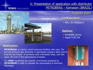
Production of Nitric Acid: • The required amount of Nitric Acid will be imported from a separate plant. Neutralization Section(Ammonium Nitrate Process)
Components: neutralizer, ammonium nitrate storage tank, mixing pipe, UAN storage tank and off-gas purification equipment • NH3containing gases from the urea plant are fed into the bottom of the mixing tube • Nitric acid is introduced somewhat lower in the circulation tube • Liquid from the circulation tube and the gas-liquid mixture in the mixing tube causes the fluid to circulate • Heat from the reaction is used for water evaporation and increase the temperature to 135C. pH controlled by adding nitric acid • Gas and liquid phases separated in the separator • Liquid sent to ammonium nitrate storage tank Neutralization Section(Ammonium Nitrate Process)
Reactions to be determined Blending Section(Mixing)
Mixing pipe components: • Urea solution, still containing some NH3 (110C) • Ammonium nitrate solution, containing 0.4% HNO3 (135C) • NH3 • nitric acid • acidic condensate from off-gas purification • heat from reaction is used to increase the temperature and evaporate water • ammonium nitrate to urea ratio is controlled at 4:3 • pH is maintained between 5-6 through the nitric acid feed • UAN solution is stored or pumped to battery limits • Off-gases from neutralizer treated in purification section Blending Section(Mixing)
Competing Processes Partial Recycle Total Recycle Once Through
The variations of these processes are found within the way the unconverted materials are handled (NH3 and CO2 for producing urea) The Core
Recycles the unconverted NH3 and CO2 through a stripping process using CO2 • The CO2strips the unconverted NH3 and CO2 from the produced UREA and recycles the unconverted material “Partial Recycle”(StamiCarbon)
Recycles all of the unconverted NH3and CO2 to the urea reactor. • Differs from stripping because the unconverted materials are recirculated into a pressurized decomposition heater. The carbamate decomposes into gaseous NH3and CO2, while excess NH3 evaporates simultaneously. This is separated by a column where NH3vapor rises and the liquefied carbamate falls; these components are then fed back to the urea reactor. “Total Recycle”(Conventional Recycle)
The unconverted NH3 is neutralizedwith acids (e.g. nitric acid) to produce ammonium salts (e.g. ammonium nitrate) as byproducts of urea production. • Disadvantages: large quantities of ammonium salt formed as byproduct and the limited amount of overall carbon dioxide conversion that can be achieved “Once Through Process”
Design Basis Specifications and Preventative Measures
Downtime • Planned vs. Unplanned • Feed • 1000tpd yearly average vs. stream average • Ambient Characteristics • Willington, ND seasonal temperatures • Average Seasonal Temperatures • Summer: May-September (70°F-80°F) • Spring: March-May (34°F-69°F) • Fall: September-November (72°F-37°F) • Winter: December-March (23°F-34°F) • Basically: It’s really cold most of the times Sources of Concern
Steam • Water • Process cooling water and tempered water • Electricity • Supplementary heating during cooler months to prevent freezing or undesirable condensation Utility Requirements
Off-gases leaving the plant must be purified Byproducts
Design Capacity • Yield • Feed Specifications • Purity • Process Specifications • UAN-32 • Temperature and Pressure Requirements • Corrosion Prevention • Safuex® Food for Thought