Download
1 / 37
370 likes | 506 Views
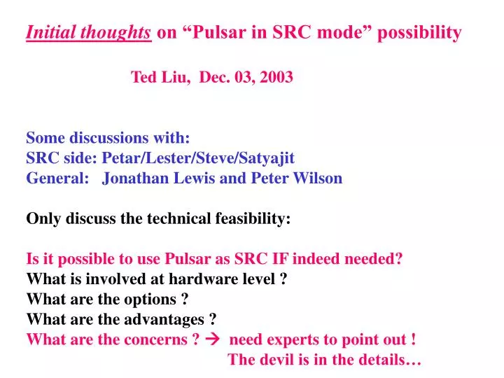
Initial thoughts on “Pulsar in SRC mode” possibility Ted Liu, Dec. 03, 2003 Some discussions with: SRC side: Petar/Lester/Steve/Satyajit General: Jonathan Lewis and Peter Wilson Only discuss the technical feasibility:

E N D
Initial thoughts on “Pulsar in SRC mode” possibility Ted Liu, Dec. 03, 2003 Some discussions with: SRC side: Petar/Lester/Steve/Satyajit General: Jonathan Lewis and Peter Wilson Only discuss the technical feasibility: Is it possible to use Pulsar as SRC IF indeed needed? What is involved at hardware level ? What are the options ? What are the advantages ? What are the concerns ? need experts to point out ! The devil is in the details…
Personal comments: a different view on Trigger/DAQ upgrade Petar is looking at the bright side, so I look at the dark side • with both SVT and L2 upgrade & UDPS, we MAY be able to • run at 40-50KHz (RunIIa-RunIIb spec), at least there • is a fair chance at low luminosity • at higher luminosity, with multiple interactions per BX, • there is a fair chance we may no longer be able to run • at 40KHz… if we are really unlucky we may still only be • able to run at <~20KHz if occupancy doesn’t scale as • one would like even after all SVT&L2 upgrade … • Enough safety margin && flexibility is crucial, • every micro-second in raw speed may matter • be prepared, and invest in raw speed&flexibility early
Some historic comments on Pulsar-SRC • Last May, after Pulsar design was finalized, Petar • & Lester asked me to see if we can make Pulsar • compatible for SRC upgrade… • I spent a few weeks to take care of that. In particular, • the RF clock & backup local clock (see next slide). • But the P3 connection was too late to change in order • to reuse the SRCTM • (bottom line: SRCTM cannot be reused if using Pulsar). • Since then, there was no more discussion on using Pulsar • to upgrade SRC… • We are now looking into this possibility again (requested • by Petar & Jonathan). maybe this time we are a bit more serious? • Backplane issue: first few empty slots of VRB P3 backplane • can be split (from the rest), or Pulsar-SRC • have to live in a different crate nearby…
Pulsar RF clock & local clock: • Use zero-delay glitch-free clock multiplexer: ICS581-01 (found by Mircea) VME chip • local clock • Tevatron RF clock • The two clocks • are arranged in • such a way that • when the RF clock • is lost, the local • clock takes over • in a few clock ticks. • The output clock • goes to PLL clock • pin on each FPGA) • Designed specifically to meet the unique requirement for SRC DataIO FPGA 1 DataIO FPGA 2 Control FPGA
Current SRC interfaces Glink To FIB Current SRC Current SRCTM VRB FIB Return LVDS Beam structure RF clock TSI(lvds) TS(Taxi, Optical) RED: already existed in Pulsar design Black: can be absorbed on a new TM, or 1-2 mezz cards Note: all LVDS interfaces use similar connectors
VRB SRCTM Current SRC
Pulsar-SRC: A few options to consider • Option A: Simplest & cleanest • rebuild the SRCTM for Pulsar, and add • TSI/beam structure/VRB interfaces on new TM. • Pulsar Control FPGA “sees&controls” everything • Option B & C: not as clean for VRB, see backup slides…
Option A: build new TM • copy the same FIB • interface design … Pulsar TM is double -width …. New SRC P3:117 signals • add TSI(LVDS)/ • TS(Taxi optical) • Beam structure/VRB… • on the other side… In this case, Control FPGA sees and controls ALL. DataIO FPGAs can be used for house-keeping work
Backplane may not be an issue: (1) Split the backplane, remove the empty slots • Pulsar-SRC and SRC can co-exist…can switch back to old SRC easily • NO need to touch • the old SRC, • Only cables … • ideal for commissioning… VRB backplane (2) Install P2 style backplane for Pulsar + new TM. (3) Pulsar-SRC and SRC can either live next to each in another VRB
Option A: build new TM (cont.) New SRC • Advantages: • simple & cleanest from firmware/hardware point of view; • DataIO FPGAs may be used for house keeping tasks; • mezzanine card slots in front can be used for • expansion/diagnostics/flexibility
Option A: build new TM (cont.) C P U New SRC • diagnostics: one possible example? just a thought last night… • can pump information into a PC and receive PC results via • either Gigabit Ethernet (round trip time ~ 30us), or • SLINKPCI (round trip ~ a few us): maybe one can try • resonance detection? either in firmware or software • Recall that Pulsar was designed for fast decisions using a PC • (firmware/hardware/software infrastructure/expertise all in place)
Other comments: • A few things to consider: • firmware design issues in each case: option A seems easiest • hardware: option A is cleanest • flexibility: Option A seems more flexible • how to commission ? think backwards! • Option A seems the best from firmware/hardware point of view • Hardware needs seem to be simple for all options. However, • one may build a Glink Rx mezzanine card as data sink for testing • purpose. Much easier this way to develop & tune the upgrade • standalone…Crucial also for Glink Single-Bit-Error • testing (down to 10**-14) … • Also keep in mind that L2-TSI interface (i.e. L2 raw decisions), • all raw L1 trigger bits as well as SVT interface all still • available on Pulsar in case someone has good ideas to use them.
Top 10 reasons why Pulsar ispotentially useful for SRC upgrade • Pulsar motherboard is designed to be compatible with SRC • Can be tailored to meet all SRC interface needs (no kludges) • P3 backplane doesn’t seem an issue • Can leave old SRC untouched, can switch back easily, • can develop & tune the upgrade standalone • One FPGA “sees&controls” all: firmware design easier/cleaner • Low level firmware can be shared, under same CVS… • Fast large SRAMs (two 128K x 36) available on board • Mezzanine card slots can be used for expansion/diagnostics • Can communicate with a PC in semi “real time” (~10 us): e.g. • resonance detection: extra safety protection for our silicon • L2 raw decision/L1 raw trigger bits/SVT interface available • Many hardware/firmware expertise/modern firmware tools… • Pulsar-SRC may be also used as a pulser for SVT … • (i.e. fake SVX fiber data into Hit Finder) for experts: Do we have good motivation(s) for SRC upgrade ???
Back up slides • Option B • Option C • the rest of slides are mostly from my SVT talk, • keep them here for background information, • also added Pulsar/PC round trip timing measurements (by Upenn) • using SLINK-PCI (slide 30-31), with web link to timing • measurements with Gigabit Ethernet More detailed information can be found at: http://hep.uchicago.edu/~thliu/projects/Pulsar
Pulsar-SRC: A few options to consider • Option A: Simplest & cleanest • rebuild the SRCTM for Pulsar, and add • TSI/beam structure/VRB interfaces on new TM. • Pulsar Control FPGA “sees&controls” everything • Option B: Simple & clean • use Pulsar TM (AUX) card. Build 1-2 types of • simple mezzanine card, with one Glink + LVDS + TAXI. Pulsar DataIO FPGAs handle FIB interfaces, and Control FPGA takes care the rest • Option C: Simple & clean (avoid the P3 backplane issue completely) • Do not use P3 and TM. Build 2 types of mezz cards: • one for FIB interfaces (2 Glink per card), the other • for the rest. One DataIO handles FIB interface, the other • takes care the rest (VRB goes from front panel, or absorb • also on mezzanine card…not as clean!)
AUX Card lvds glink lvds BEAM stru glink lvds TSI LVDS/optical glink lvds glink • DataIO FPGAs take • care the FIB interface; • Control FPGA for the rest Option B: Have FIB interface upfront, and the rest on AUX card; With 1-2 mezzanine card(s)
Option B: mezzanine card needs • only need 1 or 2 types of mezz card(s) design 1-2 types mezz card: possible absorbed in one PCB design LVDS FIB return GLINK GLINK to FIB LVDS TSI/beam structure TSI (taxi, design already exists on Pulsar mezz) TAXI optical VRB interface can be absorbed on Pulsar AUX card
If we want to keep FIB return LVDS, Glink Mezzanine card will be double-width, Pulsar-SRC will take 3 slots in this case. glink glink glink glink lvds lvds lvds No need for P3. DataIO FPGAs do most of the work: one for FIB interface, The other for the rest. VRB can be absorbed on mezzanine card lvds/taxi Option C: Have all interface upfront With two types of mezzanine cards
Pulsar is designed to be fully self-testable: at board level as well as system level For every input/output, there can be an output/input, SVT SRAMs PCI Gigabit Ethernet RF clock This allows us to develop&tune an upgrade system standalone. Pulsar design philosophy: (1) In God we trust, everything else we test; (2) One for all, and all for one;
Pulsar design: general purpose board for HEP 3 Altera APEX 20K400_652 (BGA) FPGAs 502 user IO pins each 9U VME (VME and CDF ctrl signals are visible to all three FPGAs) P1 Data IO Mezz card (CMC) connectors T S S V T P2 Control/ Merger SRAM 128K x 36 bits SLINK signal lines Data IO P3 L 1 S V T spare lines SRAM 3 APEX20K400-1XV FPGAs on board = 3 Million system gates/80KB RAM per board 2 128K x 36 pipelined SRAMs with No Bus Latency: 1 MB SRAM (~5ns access time)
Pulsar bottom view Pulsar top view
VME interface • VME interface • is based on the • same chip on all • UC boards: • e.g. GB board • VME interface • is available to • ALL three FPGAs VME chip DataIO FPGA 1 DataIO FPGA 2 Control FPGA
Pulsar clocks • each FPGA • has four clock • inputs: • (1) CDFCLK; • (2) user defined • clock (40 MHz • default, for • SLINK • interface w P3) • (2) Algorithm • clock (PLL, • tested up • to 114MHz); • OR • (4) Tevatron • RF clock • (PLL pin • on FPGAs) VME chip DataIO FPGA 1 DataIO FPGA 2 Control FPGA
SVT interfaces 1MB SRAM(2 128K x 36): 4 ns access time, pipelined NoBL SRAM SRAM: CY7C1350 VME chip DataIO FPGA 1 P2 SVT inter-comm Lines(5): Master& Slave SRAM DataIO FPGA 2 SVT data in SVT input SVT data in SRAM SVT Control FPGA SVT data in SVT output SVT data out 2 SLINK As it is, Pulsar can be used as a powerful GhostBuster board
Pulsar P3 interface P3 connection uses P2 style connector, 117 signals mapped to all 5 rows. Signal Pin map can be made compatible with AM board All signals directly visible to Control FPGA VME chip 43 signal lines each Control FPGA P3: 117 signal lines
Pulsar P2 inter-communication lines • Pulsar has five SVT style inter-communication lines on P2 visible to • all three • FPGAs. • Master • and • Slave VME chip DataIO FPGA 1 P2 DataIO FPGA 2 Control FPGA
Level 1 & TS interfaces all Level 1 trigger bits can be directly available to all FPGAs TS VME chip DataIO FPGA 1 L1 64 bits SRAM DataIO FPGA 2 SRAM Control FPGA TS interface with Control FPGA
SLINK/mezzanine interfaces Each mezzanine card has up to 83 user defined signal lines; Four mezzanine card slots up front, 2 in the back of crate. fully compatible with ATLAS DAQ/Trigger AUX card mezzanine card Mezzanine card slots can be used for expanded SRAM, FPGA, inputs/outputs etc. mezzanine card mezzanine card P3 mezzanine card Mezzanine card slots: 5V/3.3V/2.5V power provided by Pulsar
Hotlink Tx Hotlink Rx Taxi Tx Taxi Rx MOAB (Motherof All Boards) for L2 upgrade Pulsar SLINK LSC/LDC (ODIN/HOLA) AUX Card ANL SLINK->GBE
PC interface: Gigabit Ethernet / SLINK-PCI or anything one can define on AUX card • SLINK to Gigabit LSC from ANL, or SLINK LSC/LDC from CERN AUX card Netgear GA621 SLINK Tested with internal clock up to 100 MHz Oct. 21 ANL LSC NetGear GA621 SLINK LSC • Pulsar is compatible with ATLAS DAQ/trigger: via SLINK
Round-Trip timing: Performance with Gigabit Ethernet, see: http://www.hep.anl.gov/reb/cdf/risto/risto_talk.pdf
Round-Trip timing measured & the performance looks good w/ algo : Blue w/o algos : Red From CERN
P2 CDF control signals • Pulsar sees ALL P2 CDF control signals • Available to • ALL three FPGAs • can even drive • P2 backplane • if necessary VME chip DataIO FPGA 1 DataIO FPGA 2 Control FPGA
Top 10 reasons for Pulsar to bepotentially useful for SVT upgrade • Pulsar is a grandson of SVT (young & energetic); • Same P2 inter-communication lines (SVT master&slave); • SVT input is available to all three FPGAs; • fast large SRAMs (two 128K x 36) already available on board; • mezzanine card slots can be used for expansion • (extra SRAM/FPGA, extra inputs/outputs); • Back of crate (AUX) card can be used for expansion as well; • P3 interface can be made compatible with AM board; • as it is, Pulsar can be used as a powerful GhostBuster board; • with G-Link mezzanine cards, Pulsar can source/sink • SVT system (i.e. SVX fiber data) • communication within Pulsars and to new L2 decision crate • can be done with high bandwidth S-LINK • free Pulsars for SVT, this is business within family… • time to brain storm … see Alex’s talk…
Pulsar Design methodology • A major fraction of the design effort was dedicated to extensive design optimization and verification by using state-of-the-art CAD tools: • Leonardo Spectrum for VHDL synthesis; • Altera Quartus II for place and route, FPGA level simulation • Mentor Graphics QuickSim for board and multi-board level simulation; • Interconnect Synthesis tool for trace and cross talk analysis; • IS_MultiBoard tool for signal integrity checks between motherboard and mezzanine & AUX cards; • we have carefully simulated the board(s) before sending out the prototypes …
Example: Multi-board (9 boards) simulation to verify the design (top level schematics) It took 1.5 GB memory on a 2GHz/2GB modern PC to simulate 9 boards together at the same time
Pulsar Design methodology This design methodology allowed us to build flawless prototype boards The self-test capability of the board design made it possible for us to fully test (all interfaces) the prototype boards within 6 weeks after assembly. The prototype boards were also tested with on board clock speed up to 114 MHz and no problems were found. So far, Pulsar has been tested with ~ 1Billion events (Tx->Rx) without single error… No single blue wire on all five prototype board (Pulsar + four mezzanine cards) All firmware (VHDL code) in CVS