Download
1 / 23
230 likes | 472 Views
A NOVEL EFFICIENT STAND-ALONE PHOTOVOLTAIC DC VILLAGE ELECTRICITY SCHEME. A.M. Sharaf, SM IEEE, and Liang Yang Department of Electrical and Computer Engineering University of New Brunswick. PRESENTATION OUTLINE. Introduction System Model Description Novel Dynamic Error Driven PI Controller

E N D
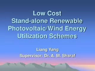
A NOVEL EFFICIENT STAND-ALONE PHOTOVOLTAICDC VILLAGE ELECTRICITY SCHEME A.M. Sharaf, SM IEEE, and Liang Yang Department of Electrical and Computer Engineering University of New Brunswick
PRESENTATION OUTLINE • Introduction • System Model Description • Novel Dynamic Error Driven PI Controller • Digital Simulation Results • Conclusions • Future Work
Introduction The advantages of PV solar energy: • Clean and green energy source that can reduce green house gases • Highly reliable and needs minimal maintenance • Costs little to build and operate ($2-3/Wpeak) • Almost has no environmental polluting impact • Modular and flexible in terms of size, ratings and applications
Maximum Power Point Tracking (MPPT) • The photovoltaic system displays an inherently nonlinear current-voltage (I-V) relationship, requiring an online search and identification of the optimal maximum power operating point. • MPPT controller/interface is a power electronic DC/DC converter or DC/AC inverter system inserted between the PV array and its electric load to achieve the optimum characteristic matching • PV array is able to deliver maximum available solar power that is also necessary to maximize the photovoltaic energy utilization in stand-alone energy utilization systems (water pumping, ventilation)
I-V and P-V characteristics of a typical PV array at a fixed ambient temperature and solar irradiation condition
The performance of any stand-alone PV system depends on: • Electric load operating conditions/Excursions/ Switching • Ambient/junction temperature (Tx) • Solar insolation/irradiation variations (Sx)
System Model Description Key components: • PV array module model • Power conditioning filter: ♦ Blocking Diode ♦ Input filter (Rf1 & Lf1) ♦ Storage Capacitor (C1) ♦ Output filter (Rf2 & Lf2 and C2) • SPWM controlled MOSFET or IGBT DC/DC dual converter (chopper) • Loads
Stand-alone photovoltaic DC/DC chopper scheme for village electricity use
Novel Dynamic Error DrivenPI Controller Three regulating loops: • The motor speed trajectory tracking loop • The The first supplementary photovoltaic current tracking loop • The second supplementary photovoltaic reference voltage tracking loop
Dynamic tri-loop error driven Proportional plus Integral control system
The global error signal (et) comprises 3-dimensional excursion vectors (ew, ei, ev)
The loop weighting factors (γw, γi and γv) are assigned to minimize the time-weighted excursion index J0 where • │Re(k)│: Magnitude of the hyper-plane error excursion vector • N= T0/Tsample • T0: Largest mechanical time constant (10s) • Tsample: Sampling time (0.2ms)
Digital Simulation Results • Stand-alone photovoltaic scheme model using the MATLAB/Simulink/SimPowerSystems software
Variation of ambient temperature (Tx) Variation of solar irradiation (Sx) Test Variations of ambient temperature and solar irradiation
Ig vs. time Vg vs. time Ig vs. time Vg vs. time Without / with dynamic controller
Pg vs. Time the increase of Pg vs. time PV power Without / with dynamic controller
The digital simulation results validate the tri-loop dynamic error driven PI Controller, ensures: • Good speed trajectory tracking with a small overshoot/undershoot and minimum steady state error • Good photovoltaic current tracking • Good photovoltaic reference voltage tracking • Maximum PV solar power/energy tracking near knee point operation can be also achieved
Conclusions • The proposed dynamic error driven controller requires only the PV array output voltage and current signals and the DC motor speed signals that can be easily measured. • The low cost stand-alone photovoltaic renewable energy scheme is suitable for village electricity application in the range of (150 watts to 15000 watts), mostly for water pumping and irrigation use in arid developing countries.
Future Work • Other PV-DC, PV-AC and Hybrid PV/Wind energy utilization schemes • New control strategies
Future Work (Continue)Novel Dynamic Error DrivenSliding Mode Controller (SMC) Three regulating loops: • The motor speed trajectory tracking loop • The dynamic photovoltaic power tracking loop
Dynamic dual-loop error-driven Sliding Mode Control (SMC) system
The loop weighting factors (γw andγp) and the parameters C0 and C1 are assigned to minimize the time-weighted excursion index J0 where • N= T0/Tsample • T0: Largest mechanical time constant (10s) • Tsample: Sampling time (0.2ms)
Thank You! & Questions?