Download
1 / 41
410 likes | 840 Views
GTSTRUDL 27 This latest version of GTSTRUDL includes numerous new features, feature enhancements, error corrections, and prerelease features. GTSTRUDL is developed and supported at: The Computer Aided Structural Engineering (CASE) Center School of Civil Engineering

E N D
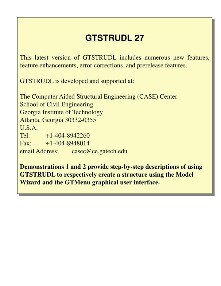
GTSTRUDL 27 This latest version of GTSTRUDL includes numerous new features, feature enhancements, error corrections, and prerelease features. GTSTRUDL is developed and supported at: The Computer Aided Structural Engineering (CASE) Center School of Civil Engineering Georgia Institute of Technology Atlanta, Georgia 30332-0355 U.S.A. Tel: +1-404-8942260 Fax: +1-404-8948014 email Address: casec@ce.gatech.edu Demonstrations 1 and 2 provide step-by-step descriptions of using GTSTRUDL to respectively create a structure using the Model Wizard and the GTMenu graphical user interface.
GTSTRUDL 27 DEMONSTRATION 1 1. This Demonstration 1 Slide Show demonstrates the use of the Model Wizard to create a simple structure using a predefined modeling template, and then using the GTMenu graphical user interface to display the structure and analysis results. 2. The slides in this Demonstration Slide Show are advanced by clicking the left mouse button, or by using the Down/Up Arrow keys, or by clicking the PgDn/PgUp (page down/up) keys. 3. The Slide Show may be exited by clicking the right mouse button. 4. Since GTMenu will occupy the full screen, the Demonstration Slide Show screen can be displayed alternately with the GTMenu screen by clicking the Alt - Tab keys at the same time.
Plane Frame Structure of Demonstration 1 • Material Steel • Member PropertiesLoads • Beams: Table: WBEAM9 1 = Self Weight • Shape: W18X35 2 = Uniform Live Load • 3 = Wind Load from Left • Columns: Table: WCOLUMN9 10 = 1 + 2 + 3 (ALL) • Shape: W14X53
Initiating GTSTRUDL 27 GTSTRUDL may be initiated from the Start menu by clicking Start - Programs - GTSTRUDL 27 - GTSTRUDL 27 as follows:
Starting GTSTRUDL in the Model Wizard When GTSTRUDL is initiated, this GT STRUDL StartupWizard opening dialog will appear with the default working directory in the Working Directory Dialog Area. The working directory may be changed if desired (e.g., C:\UserFolder). Click the Model Wizard option, and then click the OK button which opens the main GT STRUDL output window , and then opens the Model Wizard dialog box.
Click the Plane Frame option. Click the OK button. The Plane Frame Model Wizard generation template will be displayed.
Select the Force-Kilonewtons force unit menu option to change the force unit to Kilonewtons. Click the Next button.
Set geometry options to 3 bays, 2 floors, and 6 meters per bay length, and 3 meters per story height. Click the Next button.
Use the default Fixed support option. Click the Next button.
Use the default cross-section profiles of W18X35 for all beams, and W14X53 for all columns. Check the Self-Weight option for all members. Click the Next button.
Specify a uniform live load on all beams of 60 kn/m. Click the Next button.
Specify an applied wind load from the left of 50 kn. applied to each free joint on the left side of the structure. Click the Next button.
Specify an applied wind load from the left of 50 kn. applied to each free joint on the left side of the structure. Click the Next button.
The Plane Frame model is now fully specified. Click the Finish button to exit and run the resulting GTSTRUDL commands.
The result of processing the GTSTRUDL commands and data created by the Model Wizard.
Select the Analysis - Static Analysis (Stiffness Analysis) menu option to perform a linear static analysis of the structure.
Click the button in the Tool Bar in order to enter GTMenu.
In GTMenu, select the Label-Display and Label Settings menu options.
Select Label-All Joints and Label-All Members. Click the Redraw and Done buttons.
Select the View menu option. Select the Isometric View option in the View Dialog box.
In order to display a solid view of the structure: Select the Redraw Solid menu option.
Select the View menu option. Select the XY Plane, along -Z axis option in the View Dialog box.
Select the Results - Force/Moment Diagrams & Envelopes menu options. The Member Forces dialog box will appear.
Click the Select Load option in the Member Forces dialog box. Select Load 3, and click the Done button in the Current Loads dialog box.
Click the Display and Add to List button to display the Moment Z diagram for Loading 3 on all displayed members.
Click the Label button. Click the cursor at the location for which the value of Moment Z is to be displayed.
Place and click the cursor at the location on the screen where the value and location of Moment Z is to be displayed
Click the Print button in order to print a hard copy image to the current system default printer.
Select the No option since no changes were made to the structural model in GTMenu. GTMenu will now be exited, and the GT STRUDL output window will be displayed.
Select the Results - Static…..(Text Output) - Reactions menu options to list support reactions.
Click the OK button to list support reactions for All support joints.
Support reactions for All support joints and all currently active loading conditions are listed in a formatted text table in the GTSTRUDL output window.
Select the OK menu option to terminate the execution GTSTRUDL.
Select the No menu option to immediately exit GTSTRUDL. The Yes option provides for the saving of the GTSTRUDL text output created during the processing this GTSTRUDL job.
GTSTRUDL 27 DEMONSTRATION 1 - Completed This Demonstration 1 Slide Show demonstrated the use of the Model Wizard to create a simple structure using a predefined modeling template, and then using the GTMenu graphical user interface of GTSTRUDL to graphically display the structure and analysis results. GTSTRUDL 27 includes the following features: # GTMenu graphical modeling # Static frame and finite element analysis # Dynamic Analysis # Advanced Analysis including Nonlinear Static and Dynamic Analysis, Cable Analysis, Superelements, and other advanced analysis features # Steel design of frame structures # Reinforced concrete design of frame structures # Data Base Exchange (DBX) # Offshore jacket analysis and design # GTTABLE for the creation of tables of steel shape names and properties
GTSTRUDL 27 DEMONSTRATION 2 The Demonstration 2 Slide Show (accessed from the Start Menu as shown below) demonstrates the use of the GTMenu graphical user interface to create a simple structure, and then to graphically display the structure and analysis results.
GTSTRUDL 27 TUTORIALS 1, 2, and 3 Tutorials 1, 2, and 3 which are described in the GTSTRUDL User Guide: Getting Started, are additional examples of the use of GTSTRUDL, and may be accessed from the on-line Help facility in GTSTRUIDL as shown below.