Download
1 / 27
270 likes | 363 Views
Solar-B Mission Status, Operations and Planning. Len Culhane – UK EIS Principal Investigator Louise Harra – UK Project Scientist David Williams – UK EIS Chief Observer Mullard Space Science Laboratory University College London. Solar-B Spacecraft and Mission

E N D
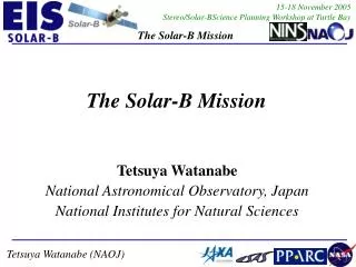
Solar-B Mission Status, Operations and Planning Len Culhane – UK EIS Principal Investigator Louise Harra – UK Project Scientist David Williams – UK EIS Chief Observer Mullard Space Science Laboratory University College London
Solar-B Spacecraft and Mission EIS Team Roles and Responsibilities UK (MSSL (PI), Birmingham, RAL): CCD cameras, Structure, On-board Processor, Filter Housing, Calibration USA (NRL, GSFC, Columbia): Optics, Coatings, Mechanisms, Filters, Japan (NAOJ, ISAS): Testing, Integration with Spacecraft Norway (UiO): EGSE and Quick-look Software All participants are involved in Post-launch Mission Operations and Data Analysis Mission Status, Operations and Planning
Solar-B Mission Instruments • Solar Optical Telescope (SOT) Largest optical telescope (d = 0.5m) to observe Sun from space Diffraction-limited (0.2 – 0.3 arcsec) imaging in range 388 – 668 nm Vector magnetic field and velocity measurement at the photosphere • X-Ray Telescope (XRT) High angular resolution ( < 2 arc sec) coronal imaging Wide temperature coverage: 1 MK < Te < 30 MK • EUV Imaging Spectrometer (EIS) Coronal raster imaging at 2 arc sec Plasma diagnostics (Te, ne, v) in 170 – 210Å and 250 – 290Å ranges Mission Status, Operations and Planning
SOT Filtergraph Fields of View • Rectangle shows the Narrowband Filter FOV, 320 x 160 arc sec with 0.08 arc • sec pixels (4096 x 2048) - inner square is 160 x 160 arc sec • Broadband Filter system • has higher magnification • (0.053 arc sec pixels) to • preserve SOT diffraction- • limited resolution • Broadband Filter FOV is • 216 x 108 arc sec • Both filter systems share • a single CCD. Mission Status, Operations and Planning
Filtergrams Broad-band Filter Imager: all 6 bands - only observable made by BFI Narrow-band Filter Imager: all 9 lines and nearby continuum Dopplergrams Images of the Doppler shift of a spectral line - line of sight velocity Derived from narrow-band filtergrams at several wavelength Longitudinal Magnetograms Location, polarity and estimate of flux for LoS magnetic field Derived from narrow-band filtergrams converted to Stokes I and V Stokes Parameters I, Q, U, V Analysis of I, Q, U, V at multiple wavelengths in a spectral line yields vector magnetograms SpectropoIarimeter scans 1.6 arc sec in 50 sec or 160 arc sec in 83 min with vector field measurement: B (longitudinal) to ± 3 Gauss B (transverse) to ± 30 Gauss Field direction to ± 1o Filtergraph Observables and Vector Magnetograms Mission Status, Operations and Planning
X-ray Telescope Response • Telescope has ~ three times greater effective area than Yohkoh SXT • Nine filters cover 1MK < Te < 30 MKwith Te resolution of D (log Te) = 0.2 • White light (G-band) solar images can be registered on the CCD at one filter • wheel position – this allows X-ray to visible image alignment • XRT observables: Full-Sun X-ray and white light images Mission Status, Operations and Planning
Large Effective Area in two EUV bands:170-210 Å and 250-290 Å Multi-layer Mirror (15 cm dia ) and Grating; both with optimized Mo/Si Coatings CCD camera; Two 2048 x 1024 high QE back illuminated CCDs Spatial resolution: 1 arc sec pixels/2 arc sec resolution Line spectroscopy with ~ 25 km/s per pixel sampling and ~ 3 – 5 km/s Doppler velocity estimates for ≥ 100 photons per line Field of View: Raster: 6 arc min×8.5 arc min; FOV centre moveable E – W by ± 15 arc min Wide temperature coverage: log T = 4.7, 5.4, 6.0 - 7.3 K Simultaneous observation of up to 25 lines/spectral windows EIS - Instrument Features Mission Status, Operations and Planning
Shift of FOV center with coarse-mirror motion Maximum FOV for raster observation 360 900 900 512 512 512 Raster-scan range 250 slot 40 slot EIS Slit: 1 or 2 arc sec EIS Field-of-View Mission Status, Operations and Planning
a) b) SOT/FPP Data c) Solar-B Mission Data Acquisition • Data are stored on-board in an 8 Gbit • mass memory • Baseline instrument memory allocations are: • - SOT/FPP → 70% • - EIS/XRT → 15% each • Data downlinked to Svalbard ground • station (ESA/Norway) on 15 orbits/day • - memory dumped once per orbit • EIS average data rate → 45 kbps • - x 5 -7 greater with lossy compression • Command uplinks only from Kagoshima • Quick-look data at ISAS and Kagoshima Mission Status, Operations and Planning
Level - 0 Reformat Solar - B Database in Japan FPP Level - 1 and -2 Reformat at Lockheed Level-0 and Cal Data Level-2 Data (FPP) Solar - B Database Solar - B Database in US in UK Solar-B Mission Data Distribution • Data distributed to UK and US in compressed level – 0 • form • Because of complexity, FPP vector • magnetogram data are transmitted in • level – 0 form to Lockheed Palo Alto • They are processed to level – 2; • vector magnetograms are then sent • to the UK and Japan Mission Status, Operations and Planning
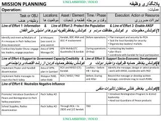
Solar-B Mission Operations • Mission operations will be conducted • from the ISAS Spacecraft Operations • Centre in Fuchinobe, Japan • Solar-B team observing plans and • community proposals will be discussed • at monthly meetings • Each instrument team will have a • Scientific Schedule Coordinator who will • organize the preparation of instrument • proposals and their integration in the • overall mission observing plan • Weekly and daily planning meetings • allow flexibility to respond to changing • solar conditions Mission Status, Operations and Planning
Data Handling and Observation Planning Mission Status, Operations and Planning
UK Data Processing, Storage and Availability Mission Status, Operations and Planning
UK Solar-B Proposal Handling Mission Status, Operations and Planning
UK Solar-B Data Centre (SDC) at MSSL • All Solar-B mission data will be archived at the SDC, stored at the Atlas Data Centre • and made available through Grid networks e.g. Astrogrid • Anticipated data volume for the three year mission life is ~ 25 Tbyte • Relevant Solar-B software will be held at the SDC and periodically updated to reflect • developments in the UK, US and in Japan • The SDC will maintain: • analysis guides on-linefor users of all three software sets • an email helpdesk and web discussion site for community support • a record of Solar-B observing plans and schedules on the centre web site • A software tool will be made available for preparation of observing proposals • The UK SSC will help in this process by assisting the UK community in making contact • with members of the other Solar-B instrument teams Mission Status, Operations and Planning
Solar-B Mission Timeline • Pre-launch period will include planning, commanding and data acquisition • rehearsals • Observing with Solar-B, using any or all of EIS, XRT and SOT/FPP, will • require the preparation of proposals • These will be presented by the UK Scientific Schedule Coordinator (SSC) to • the Solar-B team at the monthly planning meetings in Japan • Review of operations will take place 18 months after mission start • Possibility for more remote operation for Solar-B from US and UK
Following SOHO CDS, the EIS instrument will provide the next steps in EUV spectral imaging of the corona: x 10 enhancement in Aeff from use of multilayers and CCDs x 5 enhancement in spectral resolution x 3 enhancement in spatial resolution Like CDS; absolute calibration performed to ± 20% EIS will: Address a broad range of coronal science topics Enable major goals of Solar-B mission by relating coronal response to magnetic flux emergence and material flows SUMMARY Mission Status, Operations and Planning
END OF TALK Mission Status, Operations and Planning
EIS Data Flow Data compression DPCM(loss less) or 12bit-JPEG Small spectral window (25 max) CCD Readout Electronics 2Mbps max 1.3 Mbps EIS ICU S/C MDP control Observation table 250 kbps max for short duration, 40 kbps average Large hardware CCD window Average rate depends on number of downlink station. 1 slit obs. 40 slot obs. 250 slot obs. Spec.width 16 40 250 Spatial width 256" 512" 256" No. of lines 8 4 4 Compression 20% 20 % 20% Cadence 2 sec 5 sec 15 sec Rate 38.4 kbps 38.4 kbps 40 kbps Telemetry data format 10 min cadence for 44 rastering Mission Status, Operations and Planning
Comments to be added though I may not use this given its complexity – think I have a summary In words Mission Status, Operations and Planning
EIS Instrument Completed EIS Instrument Pre-Calibration Mission Status, Operations and Planning
Primary Mirror Entrance Filter CCD Camera Front Baffle Grating EIS Optical Diagram Mission Status, Operations and Planning
l/Dl ~ 4600 57.7 mÅ 58.1 mÅ 57.9 mÅ Spectroscopic Performance Long Wavelength Band • Ne III lines near 267 Å from the NRL Ne–Mg Penning discharge source • Gaussian profile fitting gives the FWHM values shown in the right-hand panel Mission Status, Operations and Planning
l/Dl ~ 4000 47 mÅ 47 mÅ Spectroscopic Performance Short Wavelength Band • Mg III lines near 187 Å from the NRL Ne–Mg Penning discharge source • Gaussian profile fitting gives the FWHM values shown in the right-hand panel Mission Status, Operations and Planning
EIS Sensitivity Detected photons per 11 area of the Sun per 1 sec exposure. Mission Status, Operations and Planning
EIS Effective Area Primary and Grating: Measured - flight model data used Filters: Measured - flight entrance and rear filters CCD QE: Measured - engineering model data used Following the instrument end-to-end calibration, analysis suggests that the above data are representative of the flight instrument Mission Status, Operations and Planning
Atomic Force Microscope Profile of Laminar Grating • AFM profile of grating grooves in a • 1 μm x 1 μm region near grating center • for grating FL-8 • . • Mean groove depth is 6.4 nm and the • land width is 108 nm(4200 lines/mm) • Grating substrates fabricated by Zeiss • - Holographic technique used to form a • sinusoidal groove pattern • - Ion beam etching used to shape laminar • grooves and to achieve specified groove depth Mission Status, Operations and Planning