Download
1 / 11
300 likes | 2.13k Views
Gain margin and phase margin. Closed-loop gain of amplifiers with feedback is replacing s=j2 π f gives the closed loop gain as a function of frequency

E N D
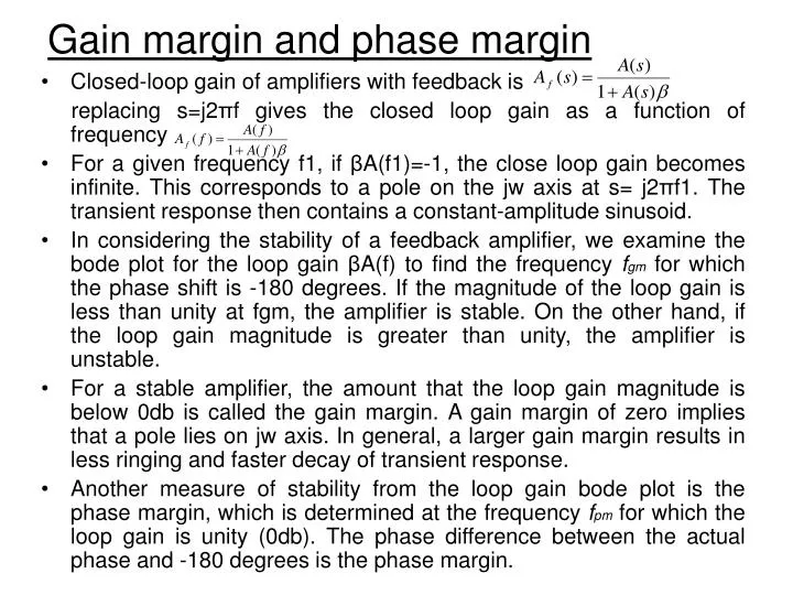
Gain margin and phase margin • Closed-loop gain of amplifiers with feedback is • replacing s=j2πf gives the closed loop gain as a function of frequency • For a given frequency f1, if βA(f1)=-1, the close loop gain becomes infinite. This corresponds to a pole on the jw axis at s= j2πf1. The transient response then contains a constant-amplitude sinusoid. • In considering the stability of a feedback amplifier, we examine the bode plot for the loop gain βA(f) to find the frequency fgm for which the phase shift is -180 degrees. If the magnitude of the loop gain is less than unity at fgm, the amplifier is stable. On the other hand, if the loop gain magnitude is greater than unity, the amplifier is unstable. • For a stable amplifier, the amount that the loop gain magnitude is below 0db is called the gain margin. A gain margin of zero implies that a pole lies on jw axis. In general, a larger gain margin results in less ringing and faster decay of transient response. • Another measure of stability from the loop gain bode plot is the phase margin, which is determined at the frequency fpm for which the loop gain is unity (0db). The phase difference between the actual phase and -180 degrees is the phase margin.
Stability of amplifier • Since we want to design feedback amplifiers to avoid transient response ringing and frequency response peaks, a generally accepted rule of thumb is to design for a minimum gain margin of 10db and a minimum phase margin of 45 degrees. • Typical magnitude and phase plot for stability consideration:
Pole compensation I • Negative feedback is useful to reduce distortion, stabilize gain and increase bandwidth. But to achieve these benefits, the loop gain • must be much larger than unity. • On one hand, we can design an amplifier with a large open-loop gain. This calls for several stages of amplification, and multi-stage amplifiers invariably introduce multiple poles. • On the other hand, a large value of feedback coefficient may lead to instability in a multiple-pole amplifier. • Thus, we must deliberately modify the pole locations (or equivalently frequency and transient response) of the amplifier before feedback can be used effectively. The is called compensation.
Pole compensation II • Instability occurs if the magnitude of loop gain is greater than 0db at the frequency for which the phase is -180. • Each pole potentially contributes a phase shift between 0 to -90 at any given frequency. • For a single amplifier, instability is not a problem, since the extreme phase is -90. • For a two pole amplifier, the extreme phase is -180, which occurs until frequency approaches infinity. However, it is possible for the phase to become very close to -180 at the frequency for which the loop gain is 0db, resulting in very small phase margin, hence long transient ringing and large frequency response peaking. • For three or more poles amplifier, a phase shift of -180 is possible before the loop gain magnitude has dropped below 0db. Thus, an amplifier having three or more poles can become unstable. • There are several approaches to compensate the pole location. One popular method, called dominant-pole compensation, is to add another pole at a very low frequency, such that the loop-gain drops to unity by the time the phase reaches X (e.g. -135 degrees). In this way, a phase margin of X+180 (e.g. 45 degrees) could be achieved.
Pole compensation III • Most of the amplifier design are OpAmp based design. • A good example for pole compensation at the concept • level is illustrated in the book Page 623, E.g. 9.11.
Before compensation After compensation
Frequency response Transient response
Three examples of IC OpAmp II http://en.wikipedia.org/wiki/Operational_amplifier