Download
1 / 35
390 likes | 632 Views
Department of Chemistry, Faculty of Science Universiti Teknologi Malaysia ______________________________ Analytical Chemistry Course SSC 1293. Chapter 5b Gas Chromatography. Outline. Introduction to GC Instrumentation Injector Oven Columns Applications. GC.

E N D
Department of Chemistry, Faculty of Science Universiti Teknologi Malaysia ______________________________ Analytical Chemistry Course SSC 1293 Chapter 5bGas Chromatography
Outline • Introduction to GC • Instrumentation • Injector • Oven • Columns • Applications
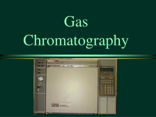
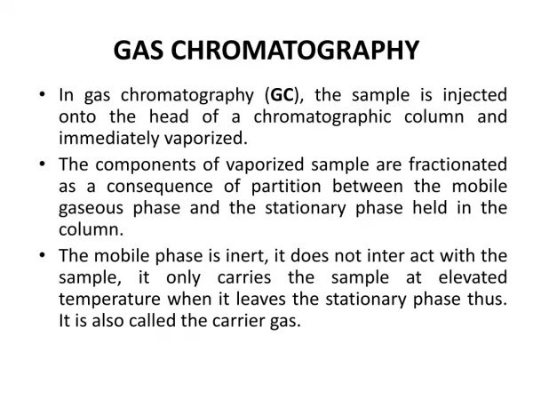
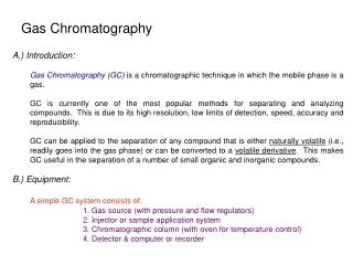
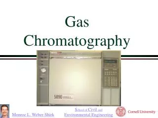
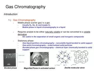
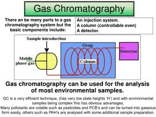
GC • A chromatographic technique that uses a gas as the mobile phase and either a liquid or solid as the stationary phase. • The analytes are adsorbed or dissolved in the stationary phase due to an equilibrium based on the vapor pressure and other additional interactive forces. • The mobile phase in GC is referred to as the carrier gas because there is little interaction between the analyte and the gas phase. • Gas-solid chromatography (GSC) uses a solid stationary phase while gas-liquid chromatography (GLC) uses a liquid stationary phase that is bonded or coated onto a solid support.
GC equipment Data handling
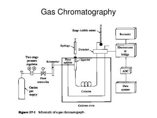
Pressure regulator Work Station Valve Detector Injector Column Oven Integrator/Plotter Carrier gas Schematic diagram of a capillary gas chromatograph Column oven .
Gases for GC • Gas type Flow rate (mL/min) • Carrier gas • N2 or He • Capillary column 1-2 • Packed Column 40 • Detector gases • Hidrogen 30 • Air 300
Split/splitless injector for GC Septum closure Septum purge Carrier gas in Valve Heater Exit Graphite ferrule Capillary column
Split Injection • Simplest method, ideal if only a limited number of components are present or trace analysis not required. • Injection port fitted with 2 valves, • one acting as a septum purge, allowing a small flow of carrier gas from just below the septum and • The second taking carrier gas from the bottom of the injection port near the column inlet. • In split mode, lower valve is used to adjust the ratio of carrier gas going to waste in the atmosphere compared to flow onto the column. • Typical ratios 10:1 to 50:1 used so that only a small proportion of the sample is transferred onto the column.
Splitless Injection • Suitable for samples containing trace compounds in low conc. – necessary to transfer as much of the sample as possible onto the column to increase sensitivity. • Lower valve is closed at time of injection and only a small septum purge flow is used. • Injection takes place into heated zone over a period of ~20 s, so that all sample is transferred to the column. • After a predetermined period (40-60 s), the lower valve is opened to purge the injection port and to prevent residual sample from causing tailing of the peaks.
Column Oven • For simple samples, separation may be carried out under isothermal conditions of constant temperature. • For samples with wide range of volatility, need to use temperature programming. • Enable volatile compound to be resolved at low temperature and elution of later less-volatile compounds to be speeded up as the temperature increases. • Profile include a series of time events – initial isothermal period, pauses at intermediate fixed temperature, different ramp rates, a final isothermal period and automated cooling-down of column to initial temperature at end of run, ready for the next cycle.
Oven Temperature Programming Final Cool-down Ramp 2 Temp Hold Inject Inject Ramp 1 Initial Ready Time
Isothermal vs temperature-programmed GC GC separation of n-alkanes using HP-101 (methylpolysiloxane) column, 50 m x 0.32 mm I.D., 0.3 m thickness. (a) Isothermal GC at 140 oC. (b) Temperature programmed GC 50 - 230 oC at 4 oC min1.
GC Columns and Stationary Phases • Heart of the chromatographic system • Determine efficiency and selectivity
GC columns: packed vs open tubular Silica Column Polyamide layer Packed column Liquid phase layer Open tubular column
Packed columns • Three components • Column tubing • Support material • Liquid stationary phase
Column tubing • Criteria Inert, thermally stable, coil up • Types Copper, stainless steel, glass • Typical sizes 1-3 m long, 1/16, 1/8,1/4 inch OD, 2-3 mm ID • Inner surface silylated To reduce interaction with polar analytes
Diatomite supportsurface Si O Si O Si OH OH OH Packing materials Liquid phase Solid support Active site Schematic diagram showing cross section of packed column comprising of solid support coated with liquid phase.
Support materials • Criteria Unreactive towards analyte and liquid phase, uniform particles and pore size • Diatomaceous earths – Chromosorb • Particle sizes Analytical column: 80-100, 100-120 mesh Preparatory column: 40-60, 60-80 mesh • Chemical treatment Acid wash (AW) – removes metallic impurities Acid wash and dimethyl dichlorosilane-treated (AW-DMCS) – remove silanol groups
Material Colour Surface (m2/g) Max. liquid loading (% w/w) Other descriptions Chromosorb G Grey 0.5 5 For polar samples Chromosorb W White 1.0 15 For polar samples Chromosorb P Pink 4.0 30 - Chromosorb T 7.5 5 Made from Teflon-6, temperature limit 250oC Chromosorb A 2.7 25 Resembles Chromosorb P, for preparative work Examples of GC support materials
Non-diatomite support materials Porous Polymers - Porapak Polymers Chromosorb 101 (PSDVB), 103 (PS) Tenax Polymers - 2,6-diphenyl-p-phenylene oxide Carbopacks support - Inertness can be manipulated Adsorbents - Molecular sieve Silica gel - inertness can be manipulated Carbon molecular sieves
Open tubular columns • No support material • Liquid phase coated on wall of column (WCOT) • Flexible fused silica Coated with polyimide layer Temp. < 350oC or else coating pyrolysed • ID: 0.1 – 0.75 mm • Film thickness: 0.1 – 5 m • Column length: 5-50 m • As ID and film thickness , sample capacity , but efficiency • Typical analytical column: 25 m x 0.22 mm x 0.25 m
Non-polar liquid phases in GLC • Hydrocarbon phases: Squalane (C30H62), Apolene (C87 hydrocarbon), Apiezon L(-(CH2)n-) - Separation of non-polar molecules:n-alkanes • Alkylsilicone liquid phases: SE-30, OV-1, OV-101 • Dimethylsilicone (-(-Si(Me)2-O-)- polymer): BP-1, Ultra-1, DB-1
GC on non-polar liquid phases 230 °C 2 °C/min 50 °C Hydrocarbons Essential oil (Cymbopogon nardus) Column: Ultra 1, 30 m x 0.25 mm x 0.25 mm
Polar liquid phases in GLC • Substituted silicone liquid phases: methylphenyl silicone - OV-105, CP-Sil 58 • Ester liquid phases: - Poly(diethylene glycol adipate) DEGA - Poly(diethylene glycol succinate) DEGS • Polyether liquid phases: • Carbowax 200 to Carbowax 20M • (Polyethylene glycol, PEG) • - HP20-M, BP-Wax, BP20
GC on polar liquid phase 230 °C Hydrocarbons 4 °C/min 50 °C Essential oil (Cymbopogon nardus) Column: HP-20M (Carbowax 20M)
Phase (Supelco) Temp. limits (oC) Equivalent phases Hewlett Packard Alltech Chrompack J&W SGE SBP-1 -60 to 320 HP-1, Ultra-1 AT-1 CP-Sil 5CB DB-1 BP-1 SPB-5 -60 to 320 HP-5, Ultra-2 AT-5 CP-Sil 8CB DB-5 BP-5 SPB-1701 Subambient to 280 HP-1701 AT-1701 CP-Sil 19CB DB -1701 BP-10 SUPELCOWAX 35 to 280 HP-Wax AT-Wax CP-Wax 52 CB DB-Wax BP-20 Petrocol 50.2 (Petroleum) -60 to 320 PONA - Squa-lane - PONA PTE-5 (Environmental) -60 to 320 HP-5 MS - - DB-5.625 BPX-625 SPB-608 (Pesticides) Subambient to 300 HP-608 AT-Pesticide CP-Sil 8CB DB-608 BP-608 Comparison of Manufacturers’ Phases
Factors in selecting stationary phase • Nature of analyte • Stationary phase type • Column internal diameter • Film thickness • Column length
Effect of column internal diameter (ID) Open Tubular Packed Column
Column conditioning • Condition at • 20 oC higher than analysis temp • at least 10-20 oC less than stated max. operational temp of phase • Never condition at column’s max temp • Program temp slowly to conditioning temp (2-4 oC/min) • Cool down slowly (nonbonded phase) • Purge column with carrier gas for 1/2 hr before heating over • Very high carrier gas flows can be used for conditioning • Conditioning time varies with your need
GC Applications • Petrochemical • Environmental • Forensic • Pharmaceutical • Oleochemical • Others
Peak No. Components Kovats Index 1 Nonane 900 2 Decane 1000 3 Undecane 1100 4 Naphthalene 1182 5 Dodecane 1200 6 Tridecane 1300 7 1-methyl naphthalene 1322 8 Tetradecane 1400 9 Pentadecane 1500 10 Hexadecane 1600 11 Heptadecane 1700 12 Pristane 1712 13 Octadecane 1800 14 Phytane 1816 15 Nonadecane 1900 16 Cosane 2000 17 Uncosane 2100 18 Docosane 2200 19 Tricosane 2300 20 Tetracosane 2400 GC Profile of Diesel • ..
GC-ECD SEPARATION OF PCB . GC Conditions: HP-5MS capillary column, Injection port temperature at 280oC and detector temperature at 290 oC. Temperature programming from 200oC (held for 3 minutes) then ramped to 230 oC (held for 3 minutes) at a rate of 5 oC/min and increased to 260 oC (held for 3 minutes) at a rate of 2 oC/min. Peak identity: (1) iso-octane (2) PCB 28, (3) PCB 52, (4) PCB 35, (5) PCB 101, (6) PCB 118, (7) PCB 153, (8) PCB 138 and (9) PCB 180.
GC-ECD SEPARATION OF NITROEXPLOSIVES Initial oven temperature at 100 oC, held for 2 min then ramped to 250 oC at 15 oC/min and held for 1 minute. The injector temperature and detector temperature at 230 oC and 300 oC. GC column was Ultra 2 (25 m x 0.20 mm ID x 0.11 µm film thickness). helium as carrier gas (1 mL/min) and nitrogen as make-up gas (30 mL/min).