Download

1 / 39
390 likes | 532 Views
Plans for an Aeroelastic Prediction Workshop Jennifer Heeg, Josef Ballmann , Kumar Bhatia, Eric Blades, Alexander Boucke, Pawel Chwalowski, Guido Dietz, Earl Dowell, Jennifer Florance, Thorsten Hansen, Mori Mani, Dimitri Mavriplis, Boyd Perry, Markus Ritter, David Schuster,

E N D
Plans for an • Aeroelastic Prediction Workshop • Jennifer Heeg, Josef Ballmann, Kumar Bhatia, Eric Blades, • Alexander Boucke, Pawel Chwalowski, Guido Dietz, • Earl Dowell, Jennifer Florance, Thorsten Hansen, Mori Mani, • Dimitri Mavriplis, Boyd Perry, Markus Ritter, David Schuster, • Marilyn Smith, Paul Taylor, Brent Whiting, and • Carol Wieseman • AeroelasticPW@gmail.com • https://c3.ndc.nasa.gov/dashlink/projects/47/ 15th International Forum on Aeroelasticity & Structural Dynamics June 26-30, 2011 Paris
Acknowledgments Funding of NASA participation, geometry generation & workshop organization NASA Subsonic Fixed Wing Program Funding of Workshop organization NASA Engineering & Safety Center HIRENASD Research Project Aachen University HIRENASD Project Funding German Research Foundation (DFG) Grid Generation Ansys, ATA, Georgia Tech, Technion University, ISCFDC, NASA Organizing Committee Roster
OUTLINE • Overview • Configurations • RSW • BSCW • HIRENASD • Participation
Objectives of AePW Assess state-of-the-art Computational Aeroelasticity(CAe) methods as practical tools for the prediction of static and dynamic aeroelastic phenomena and responses on relevant geometries • Perform comparative computational studies on selected test cases • Identify errors & uncertainties in computational aeroelastic methods • Identify gaps in existing aeroelastic databases • Provide roadmap of path forward • Additional existing data sets? • New experimental data sets? • Analytical methods developments?
Guiding Principles • Provide an impartial international forum for evaluating the effectiveness of CAe methods • Promote balanced participation across academia, government labs, and industry • Use common public-domain subject geometries, simple enough to permithigh-fidelity computations • Provide baseline grids and baseline structural models to encourage participation and help reduce variability of CAe results • Openly discuss and identify areas needing additional research and development • Conduct uncertainty quantification analyses of CAe results to establish confidence levels in predictions • Schedule open-forum sessions to further engage interaction among all interested parties • Maintain a public-domain-accessible database of geometries, grids, and results • Document workshop findings; disseminate this information through publications and presentations
Building block approach to validation • Utilizing the classical considerations in aeroelasticity • Fluid dynamics • Structural dynamics • Fluid/structure coupling Structuraldynamics Unsteady aerodynamic pressures due to forced modal oscillations Deformed shape, Structural motion, Boundary conditions Load Distribution, Magnitude, Phasing Fluid dynamics Validation Objective of 1st Workshop • Future Workshops • Directed by results of this workshop • Directed by big-picture assessment of needs & interests
1st AePW to be held weekend beforethe next AIAA SDM conferenceApril 21-22, 2012 • Presentations by workshop participants • No formal AIAA papers • Prior commitment & data submission required for presentation • Attendance & forum discussions open to all (separate registration from SDM conference)
Aeroelastic Prediction Workshop Schedule • Identified organizing committee: Dec 1, 2010 • Data Release & Workshop Kickoff: IFASD 2011, Paris • 10 months to perform computations • Workshop: April 2012 Kickoff at IFASD Workshop at 2012 SDM FY= USGovt Fiscal Year, Oct-Oct (e.g. FY12 – Oct 2011-Oct 2012)
OUTLINE • Overview • Configurations • RSW • BSCW • HIRENASD • Participation
Configurations Selected • Rectangular Supercritical Wing • Benchmark Supercritical Wing • High Reynolds number Aero-Structural Dynamics Model
Rectangular Supercritical Wing (RSW) • Simple, rectangular wing • Fixed transition, 6% chord • Structure treated here as rigid • Forced oscillation pitching motion about the 46% chord • Highest angle of attack case available was chosen to stress the capabilities of the steady analysis • Corresponding experimental data available to analysts • M=0.825, Rec=4.0 million, test medium: R-12 • Steady Cases • α = 2° • α = 4° • Dynamic Cases • α = 2°, θ = 1.0°, f = 10 Hz • α = 2°, θ = 1.0°, f = 20 Hz
RSW Model splitter plate Splitter plate • Known deficiencies: • Splitter plate deficiencies • Small size • Located in the tunnel wall boundary layer • 6” off of the wall • Estimated boundary layer thickness: 12”
RSW Model Layout and Airfoil Shown as mounted in the wind tunnel Oscillated in pitch about the 46% chord Dimensions in inches & (millimeters) 12% thick supercritical airfoil Experimental data acquired in R-12 @ Rec = 4 million, Mach=0.825
RSW: Coordinate system, Instrumentation Unsteady Pressure Measurements 4 chords (30.9, 58.8, 80.9, and 95.1 % span) 29 pressure per chord (14Upper, 14 Lower)
Benchmark Supercritical Wing (BSCW) • Simple, rectangular wing • Fixed transition at 7.5% chord • Structure treated here as rigid • Data acquired under mixed attached/separated flow conditions • Time history data available • Large, well-positioned splitter plate • 40” from wall • Boundary layer measured as 8”-14” • Additional studies and data available on this splitter plate Known deficiencies: • Limited number of pressure transducers in experimental data • Mach number is at edge of acceptable range for quality pressure data with splitter plate • M=0.85, Rec=4.49 million, test medium: R-134a • Steady Case • α = 5° • Dynamic Cases • α = 5°, θ = 1°, f = 1 Hz • α = 5°, θ = 1°, f = 10 Hz Semi-blind test case- no additional experimental data made available to analysts
BSCW Geometry and Test Configuration • Unsteady Pressure Measurements • 1 chord at 60% span • 40 sensors • 22 upper surface • 17 lower surface • 1 leading edge Forced oscillation: Pitching motion about 30% chord Dimensions in inches NACA SC(2)_0414 supercritical airfoil Experimental data acquired in R-134a @ q = 200 psf, Rec = 4.49 million, Mach=0.85
BSCW Data Semi-blind test case- no additional experimental data made available to analysts • M=0.85, Rec=4.49 million, test medium: R-134a • Steady Case • α = 5° • Dynamic Cases • α = 5°, θ = 1°, f = 1 Hz • α = 5°, θ = 1°, f = 10 Hz
BSCW Structural Properties • Designed as a rigid wing on a rigid mounting system. • Mounting system oscillates wing in pitch about 0.30 chord. • Structural frequencies of installed wing and mounting system: • 24.1 Hz spanwise (Wing flapping) • 27.0 Hz in-plane. • 79.9 Hz torsion
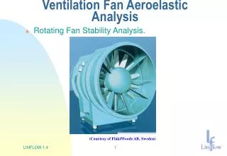
HIRENASD HIRENASD funded by DFG • 3-D aeroelastic wing with generic fuselage model • Fixed transition • Treated as aeroelastic here • Relatively weak aeroelastic coupling • Forced oscillation at 2nd bending mode frequency • Time history data available • Data includes • Balance loads • Mean and fluctuating pressure data • Limited set of surface deformation Known deficiencies: • Limited deflection data • Only excited at natural frequencies • M = 0.80, test medium: nitrogen • Steady (Static Aeroelastic) Cases • Rec= 7.0 million, α = 1.5° • Rec = 23.5 million, α = -1.34° • Dynamic Cases: forced oscillation at 2nd Bending mode frequency • Rec= 7.0 million, α = 1.5° • Rec= 23.5 million, α = -1.34°
HIRENASD Windtunnel Model andAssembly funded by DFG suction side view
HIRENASD Measuring Equipment for Pressure funded by DFG Pressure Sensors: 259 unsteady pressure sensors distributed at 7 span stations
AePW Dataset Selection • Rectangular Supercritical Wing: (M=0.825, Rec=4.0 million, test medium: R-12) • Steady Cases • α = 2° • α = 4° • Dynamic Cases: forced pitching oscillation (α = 2°, θ = 1.0°) • f = 10 Hz. • f = 20 Hz. • Benchmark SuperCritical Wing (Semi-Blind) (M=0.85, Rec=4.49 million, test medium: R-134a) • Steady Case • α = 5° • Dynamic Cases: forced pitching oscillation (α = 5°, θ = 1°) • f = 1 Hz • f = 10 Hz • HIRENASD (M = 0.80, test medium: nitrogen) • Steady Cases • Rec = 7.0 million, α = 1.5°, static aeroelastic • Rec = 23.5 million, α = -1.34°, static aeroelastic • Dynamic Cases: forced oscillation at 2nd Bending mode frequency • Rec = 7.0 million, α = 1.5°, f= 78.9 Hz • Rec = 23.5 million, α = -1.34°, f=80.3 Hz
OUTLINE • Overview • Configurations • RSW • BSCW • HIRENASD • Participation • Invitation to participate • Data provided to participants • Data expected from participants
Invitation to participate AePW email address: AeroelasticPW@gmail.com • Go to • https://c3.ndc.nasa.gov/dashlink/projects/47/ • To sign up for • Email distribution list Click • Workshop participation Click
Participant Information Sources • Workshop website: with downloads of grids, geometry, structural model, etc • https://c3.ndc.nasa.gov/dashlink/projects/47/ • Links to: • HIRENASD website (German and English languages) • http://www.lufmech.rwth-aachen.de/HIRENASD/ • https://heinrich.lufmech.rwth-aachen.de/index.php?lang=en&pg=home • Drag and High-Lift Prediction Workshops • http://aaac.larc.nasa.gov/tsab/cfdlarc/aiaa-dpw/ • http://hiliftpw.larc.nasa.gov/
Summary of AePW Grids GRID TYPE Unstructured Structured Overset Node Based Cell Centered Hex Multiblock Configuration Mixed Tetrahedra Mixed Tetrahedra C M F C M F C M F C M F C M F C M F RSW √ ○ ○ ○ √ √ √ √ √ √ BSCW ⨀ ⨀ ○ ○ ○ ⨀ ○ ○ ○ HIRENASD √ √ √ √ √ ○ ○ ○ √ = Complete ⨀ = In process ○ = Desired
Thorsten Hansen Ansys RSW Grids SolidMesh: Mixed Elements Unstructured Grids SolidMesh: Structured Hexahedral Grid Marilyn Smith Georgia Institute of Technology
Thorsten Hansen Ansys BSCW Grids SolidMesh: Mixed Elements Unstructured Grids SolidMesh: Structured Hexahedral Grid (to be generated) Eric Blades ATA Engineering, Inc.
Overview of the coarse, medium, and fine unstructured HIRENASD meshes • Coarse: • 5.7 Million Total Nodes • 14.4 Million Total Elements • Boundary layer cells: • 34 prism layers • Stretching factor 1.28 • Medium: • 16.05 Million Total Nodes • 38.9 Million Total Elements • Boundary layer cells: • 40 prism layers • Stretching factor 1.25 • Fine: • 46.4 Million Total Nodes • 104.6 Million Total Elements • Boundary layer cells: • 45 prism layers • Stretching factor 1.23 M. Ritter, German Aerospace Centre - Göttingen
Aeroelastic Prediction WorkshopStructured Grids Thorsten Hansen ANSYS Germany thorsten.hansen@ansys.com
HIRENASD Overset Mesh with Chimera (Medium-Size Mesh) fuselage zone world zone wing zone wing-fuselage collar zone
Comparison Data Matrix An ascii template will be provided for submission of data
Example of grid convergence data: Lift coefficient vs convergence parameter Ref High Lift Prediction Workshop, Rumsey & Slotnik
Example of steady data: Steady pressure coefficient for HIRENASD Data for Steady Rigid cases will be similar, but without Static Aeroelastic results
HIRENASD Frequency Responses at 2nd Bending Mode Frequency (78.9 Hz) Cp(x)/displacement Pressure coefficients at span station 4 due to displacement at location (15,1) Reference quantity: Displacement at location (15,1)
We are actively seeking participation from the technical community We look forward to working with you to better define and advance the state of the art in computational aeroelasticity
Case 1 Selection RationaleRectangular Supercritical Wing (RSW) • Cases chosen to focus on the steady and unsteady aerodynamic solutions and their variation. • Mach 0.825 generates transonic conditions with a terminating shock; highest Mach number with forced transition • Steady Data: Two static angles of attack chosen • α = 2.0°generates a moderate-strength shock with some potential for shock-separated flow; corresponding forced oscillation data exists. • α = 4.0°generates strong shock with greater potential for shock-separated flow . • Unsteady Data: Two forced oscillation frequencies chosen to evaluate methods abilities to distinguish frequency effects. • Non-zero mean AoA introduces a wing loading bias for which code-to-code comparisons can be accomplished.
Case 2 Selection RationaleBenchmark Supercritical Wing (BSCW) • Highly nonlinear aerodynamic phenomena. • Known shock-separated transient flow. • Relatively obscure data that serves as a virtually blind test case for the methods. • Better data detail and insight than for RSW. • Statistical and time-history data are available for comparison. • Good possibilities for retesting for future workshops.
Case 3 Selection RationaleHIRENASD Wing • Aircraft-representative geometry, rather than “unit problem” • Initial test for fully coupled aeroelastic analysis. • Steady cases demonstrate prediction capabilities for static aeroelastic problems. • Dynamic cases demonstrate structural dynamics coupling with unsteady aerodynamics techniques. • Relatively weak aeroelastic coupling make it a good entry-level aeroelastic test case.