Download
1 / 63
630 likes | 639 Views
This article explores the V-I relationships for resistors, inductors, and capacitors in AC circuits, including their phase differences and phasor representations.

E N D
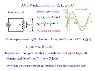
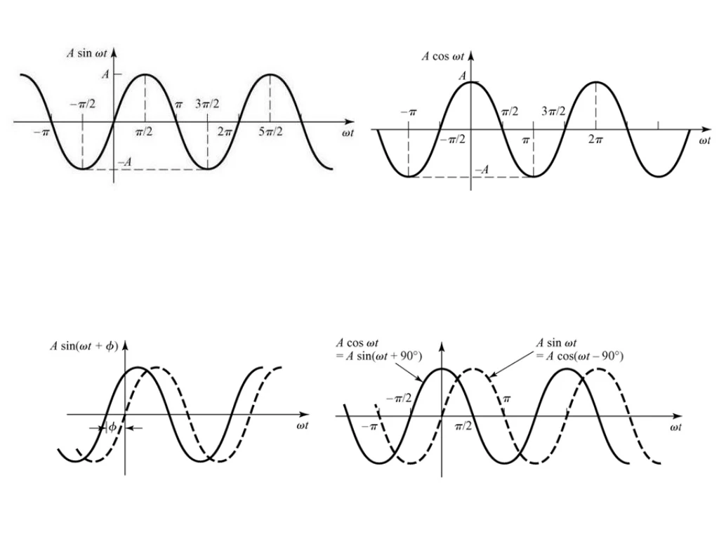
The V-I Relationship for a Resistor Let the current through the resistor be a sinusoidal given as Is also sinusoidal with amplitude amplitude And phase The sinusoidal voltage and current in a resistor are in phase
The V-I Relationship for an Inductor Let the current through the resistor be a sinusoidal given as Now we rewrite the sin function as a cosine function The sinusoidal voltage and current in an inductor are out of phase by 90o The voltage lead the current by 90oor the current lagging the voltage by 90o
The V-I Relationship for a Capacitor Let the voltage across the capacitor be a sinusoidal given as Now we rewrite the sin function as a cosine function The sinusoidal voltage and current in an inductor are out of phase by 90o The voltage lag the current by 90oor the current leading the voltage by 90o
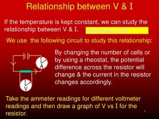
The Sinusoidal Response KVL This is first order differential equations which has the following solution We notice that the solution is also sinusoidal of the same frequency w However they differ in amplitude and phase
Complex Numbers Rectangular Representation
Complex Numbers (Polar form) Rectangular Representation
Euler’s Identity Euler’s identity relates the complex exponential function to the trigonometric function Adding Subtracting
Euler’s Identity The left side is complex function The right side is complex function The left side is real function The right side is real function
Complex Numbers (Polar form) Rectangular Representation Short notation
Real Numbers Rectangular Representation Polar Representation OR
Rectangular Representation Polar Representation OR
Imaginary Numbers Rectangular Representation Polar Representation OR
Rectangular Representation Polar Representation OR
Complex Conjugate Complex Conjugate is defined as
Complex Numbers (Multiplication) Multiplication in Rectangular Form Multiplication in Polar Form Multiplication in Polar Form is easier than in Rectangular form
Complex Numbers (Division) Divisionin Rectangular Form
Complex Numbers (Division) Divisionin Polar Form Division in Polar Form is easier than in Rectangular form
Complex Conjugate Identities ( can be proven) OR Other Complex Conjugate Identities ( can be proven)
Let the current through the indictor be a sinusoidal given as Let the current through the indictor be a sinusoidal given as From Linearity if then
The V-I Relationship for an Inductor Let the current through the resistor be a sinusoidal given as Now we rewrite the sin function as a cosine function The sinusoidal voltage and current in an inductor are out of phase by 90o The voltage lead the current by 90oor the current lagging the voltage by 90o
From Linearity if The solution which was found earlier
The solution is the real part of This will bring us to the PHASOR method in solving sinusoidal excitation of linear circuit
The real part is the solution Now if you pass a complex current Phasor You get a complex voltage Phasor
The phasor The phasor is a complex number that carries the amplitude and phase angle information of a sinusoidal function The phasor concept is rooted in Euler’s identity We can think of the cosine function as the real part of the complex exponential and the sine function as the imaginary part Because we are going to use the cosine function on analyzing the sinusoidal steady-state we can apply
Moving the coefficient Vm inside Phasor Transform Were the notation Is read “ the phasor transform of
The V-I Relationship for a Resistor Let the current through the resistor be a sinusoidal given as Is also sinusoidal with amplitude amplitude And phase The sinusoidal voltage and current in a resistor are in phase
Now let us see the pharos domain representation or pharos transform of the current and voltage and Which is Ohm’s law on the phasor ( or complex ) domain
The voltage and the current are in phase Imaginary Real
The V-I Relationship for an Inductor Let the current through the resistor be a sinusoidal given as The sinusoidal voltage and current in an inductor are out of phase by 90o The voltage lead the current by 90oor the current lagging the voltage by 90o You can express the voltage leading the current by T/4 or1/4fseconds wereTis the period and fis the frequency
Now we rewrite the sin function as a cosine function ( remember the phasor is defined in terms of a cosine function) The pharos representation or transform of the current and voltage But since Therefore and
and The voltage lead the current by 90oor the current lagging the voltage by 90o Imaginary Real
The V-I Relationship for a Capacitor Let the voltage across the capacitor be a sinusoidal given as The sinusoidal voltage and current in an inductor are out of phase by 90o The voltage lag the current by 90oor the current leading the voltage by 90o
The V-I Relationship for a Capacitor The pharos representation or transform of the voltage andcurrent and
and The voltage lag the current by 90oor the current lead the voltage by 90o Imaginary Real
Phasor ( Complex or Frequency) Domain Time-Domain
Impedance and Reactance The relation between the voltage and current on the phasor domain (complex or frequency) for the three elements R, L, and C we have When we compare the relation between the voltage and current , we note that they are all of form: Which the state that the phasor voltage is some complex constant ( Z ) times the phasor current This resemble ( شبه) Ohm’s law were the complex constant ( Z ) is called “Impedance” (أعاقه ) Recall on Ohm’s law previously defined , the proportionality content R was real and called “Resistant” (مقاومه ) Solving for ( Z ) we have The Impedance of a resistor is In all cases the impedance is measured in Ohm’s W The Impedance of an indictor is The Impedance of a capacitor is
Impedance The Impedance of a resistor is In all cases the impedance is measured in Ohm’s W The Impedance of an indictor is The Impedance of a capacitor is The imaginary part of the impedance is called “reactance” The reactance of a resistor is We note the “reactance” is associated with energy storage elements like the inductor and capacitor The reactance of an inductor is The reactance of a capacitor is Note that the impedance in general (exception is the resistor) is a function of frequency At w = 0 (DC), we have the following short open
9.5 Kirchhoff’s Laws in the Frequency Domain ( Phasor or Complex Domain) Consider the following circuit PhasorTransformation KVL Using Euler Identity we have Which can be written as Factoring Can not be zero Phasor KVL on the phasor domain So in general
Kirchhoff’s Current Law A similar derivation applies to a set of sinusoidal current summing at a node Phasor Transformation KCL KCL on the phasor domain
Example 9.6 for the circuit shown below the source voltage is sinusoidal (a) Construct the frequency-domain (phasor, complex) equivalent circuit ? (b) Calculte the steady state current i(t) ? The source voltage pahsor transformation or equivalent The Impedance of the indictor is The Impedance of the capacitor is