Download
1 / 66
660 likes | 664 Views
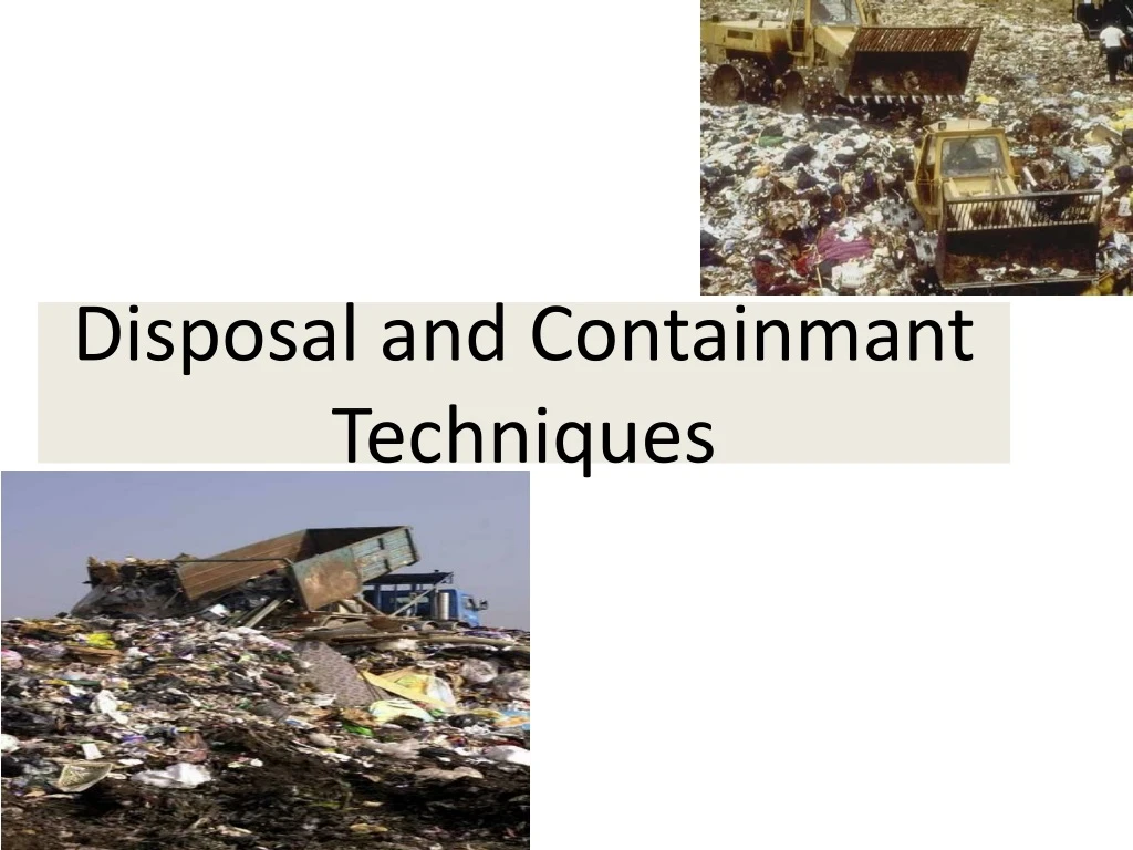
Disposal and Containmant Techniques. Selection of sites for Waste Disposal facilities. Receptor related attributes Population with in 500 m Distance to nearest drinking well Use of site by nearby residents Distance to nearest office building Land use Critical Environment.

E N D
Selection of sites for Waste Disposal facilities • Receptor related attributes • Population with in 500 m • Distance to nearest drinking well • Use of site by nearby residents • Distance to nearest office building • Land use • Critical Environment
2. Pathway related Attributes • Distance to nearest surface water • Depth to ground water • Type of contamination • Precipitation • Soil permeability • Bed Rock Permeability • Depth to bed rock • Susceptability to erosion and runoff • Climatic factors relating to air pollution • Susceptibility to seismic activity
3.Waste and related attributes • Toxicity • Radioactivity • Ignitability • Reactivity • Corrosivity • Solubility • Volatility
4.Waste Management related attributes • Physical state • Waste quantity • Waste compatibility • Use of liners • Gas Treatment • Leachate Treatment • Site security • Safety measures
Site investigation criteria • Sub Soil Investigation: type of soil, depth of GWT and bedrock, permeability of various strata, strength parameters, extent of availability of liner materials • Ground Water / Hydro geological Investigation: Depth of GWT, GW flow direction, Baseline GW quality parameters • Topographical Investigation: To compute the earth work quantities precisely • Hydrological Investigation: To estimate the quantities of runoff for appropriate design of drainage facilities • Geological Investigation and Seismic Investigation: to delineate the bedrock profile beneath the landfill base
Hydrogeological aspects of selection of waste disposal sites • CONDITIONS AT THE SITE • PROVISION OF DATA FOR DESIGN AND MANAGEMENT OF WASTE DISPOSAL FACILITIES
Assessment of regional and local geology • Assessment of local surface hydrology • Identification of main hydrogeological units (aquifers,aquiclude etc) • Ground water mechanisms • Local structural features • Measuring GWL and hyraulic gradient • Estimating hydraulic conductivity • Ground water chemistry • Surface and ground water receptors of contamination • Present and future development of GW • Characteristics of materials present in saturated and unsaturated zones
Changes Occurring in a Waste Dump Biological Changes • During the aerobic decomposition, carbondioxide is the principal gas produced. • Once the available oxygen has been consumed, the decomposition becomes anaerobic and the organic matter is converted to • Carbondioxide • Methane • Trace amounts of ammonia • Hydrogen sulfide • Many other chemical reactions are also biologically initiated therefore it is difficult to define the condition that will exist in any waste dump at any stated time.
The chemical reactions that occurs in a waste dump are • Dissolution • Suspension of waste materials • Biological conversion products in the liquid percolating through the waste • Evaporation and vaporization of chemical compounds • Sorption of volatile and semi volatile organic compounds into the waste material • Decomposition of organic compounds • Oxidation-reduction reactions affecting metals and the solubility of metal salts. • The dissolution of biological conversion into the leachate is of special importance because these materials can be transported out of the waste dump with the leachate. Chemical Changes
The important physical changes in waste dumps are • Lateral movement of gases in the waste • Emission of gases to the surrounding environment • Movement of leachate within the waste and into underlying soils • Settlement caused by consolidation and decomposition of the waste. Physical Changes
SUBSURFACE DISPOSAL TECHNIQUES • Deep wells • Injection wells • Mine Shafts • Entrenchment • Landfills
1.Deep-well Disposal In rock (not soil), isolated from freshwater aquifers; waste is injected into a permeable rock layer hundreds to thousands of meters below the surface. Deep-well injection of oil-field brine has been important to control water pollution in oil fields for many years.
USES • Petroleum industries- recovery of oil and for brine waste
2.INJECTION WELL DISPOSAL • Deep-well injection system -- disposal in sandstone or fractured limestone capped by impermeable rock and isolated from fresh water. Monitoring wells are a safety precaution. • Disposal of hazardous waste • Hazardous liquid waste placed in well confined geological formations that are deep below earths surface
Deep well injection directly introduces liquids into a deep aquifer in the subsurface environment via pressurized wells. • CLASS I WELLS - used for disposal of hazardous and non-hazardous industrial or municipal wastes. • CLASS II WELLS - used for injection of oil field brines and other hydrocarbon wastes. • CLASS III WELLS - used for solution mining processes. • CLASS IV WELLS - those which historically disposed of radioactive wastes (this is no longer done). • CLASS V WELLS - used for any activity not mentioned above, such as geothermal steam mining operations.
Parameters- Construction of deep wells • Low pressure • Large area extent • High porosity and permeability • Nature of aquifer • Seperation from freshwater horizon • Geological strata • Type of waste
3. MINE SHAFTS • Solidified waste packed in non breakable containers ( concrete cylinders, drums) • These are transported down the shafts placed in chambers • Chambers sealed • Indefinite life- unless corroded from inside • Sites chosen – Salt, potash and gypsum deposits
4.Entrenchment • Modified landfill method • Refuse placed in trenches & buried • Trenches- 3m deep, 1mwide, 10m long • Monitored for 24 months • If made in clayey soil- no problems of GW contamination & odour problem • Sites can be used for vegetable production
The components of the engineered landfill are • Liner system • Leachate collection and treatment facility • Gas collection and treatment facility • Final cover system • Surface water drainage system • An environmental monitoring system • A closure and post closure plan
PHASES OF LANDFILL PROJECT 1. Siting 2. Designing 3. Construction 4. Operation 5. Closure of landfill
1. SITING A LANDFILL Topography • Alluvial/ sedimentary formations suitable • Base above saturation zone • Prevent standing water • Prevent erosion and runoff • Excessive sloping (1% but less than 10%)
Climate • Low rainfall • High surface evaporation rates Groundwater • Location and quality Flood plains • Outside floodplains Surface water • Prevent runoff
Air quality • Monitored • Controlled Availability of transport system • Convenient transport facilities Hydrogeology • Low permeability ( not exceed 107 cm/s) • Texture of soil • Fine grained soil – low Leachate penetration
2. DESIGNING-Landfill Section Depending on: • Topography of the area • Depth of ground water table • Availability of suitable daily cover material. 1.Above ground landfills Above ground landfills are used in those areas where GWT is high. -Used when terrain is unsuitable for excavations
2.Below ground landfill • suitable for areas where adequate cover material is available and GWT is not near the surface. • Solid waste dumped in trenches excavated in soil • Trenches- • Length :100 to 300m • Depth: 3 m • Width :5 to 15 m • Side slope : 2:1
3.Above and below ground landfill-------- 4.Slope landfill ------------------------------ 5.Valley landfills----------------------------
Implications of Disposal Above, On and Below Ground Surface • Advantage • Drainage of leachate is by gravity. • Thickness of unsaturated zone below the landfill is large. • Landfill is conspicuous and thus cannot be ignored. • Poor surface drainage due to settlement of final landfill surface can be avoided. • Inspection of the entire facility i.e. final cover, leachate collection system and gas collection system is easier. Above Ground Landfills • Disadvantage • They alter the land use pattern of the area. • They have more surface area exposed to elements of nature such as wind, rain and require significant erosion control measures.
On and Just Below Ground Surafce • Disadvantage • Leachate collection through regular pumping. • Require good surface water drainage measures if located in low lying areas and are closer to ground water table than above ground landfills. Advantage • More waste can be stored per unit land area in comparison to above ground landfills. • Efficient use can be made of the excavated material but using it as landfill cover. • Productive use of the flat landfill surface can be made on completion of landfill. • Long term slope stability and erosion control requirements are not very critical in such landfills.
Landfills Deep Beneath the Earth’s Surafce • Wastes can also be dumped in underground openings, tunnels or caverns, however the cost of construction in such cases is extremely high. • If the disposal is in soil where water table is high, the waste would always be surrounded by ground water and, irrespective of the multiple barriers used for waste isolation, the potential of ground water contamination would always be high.
If waste is disposed in strong competent rock: the very low permeability of the rock mass coupled with multiple barriers layers ensures long term containment of the waste. • Such disposal techniques are adopted for extremely hazardous waste • Waste disposal deep beneath the ground surface has the least impact on the land use pattern.
Landfill Layout A landfill site will comprise of the area in which the waste will be filled as well as additional area for support facilities. With in the area to be filled, work may proceed in phases with only a part of the area under active operation.
Main Design Phase The main design phase includes • Design of liner, leachate collection and Treatment • Gas Collection and Treatment • Cover System • Landfill Stability • Surface Water Drainage • Environmental Monitoring
a. Phase:- • sub area of the landfill. • consists of cells, lifts, daily cover, intermediate cover, liner and leachate collection facility, gas control facility and final cover over the sub-area. • designed for a period of 12 to 18 months. b. Cell:- • volume of material placed in a landfill during one operating period usually one day.