Download
1 / 24
240 likes | 249 Views
PC Based Camera Tilt-pan System and Target Coordinate Calculation. STUDENT: ADVISER: CO-ADVISER :. G/C BADAR S/L OMAR BASHIR S/L SOHAIL. BACKGROUND. Fixed camera was used previously that will be replaced by tilt pan system.

E N D
PC Based Camera Tilt-pan System and Target Coordinate Calculation STUDENT: ADVISER: CO-ADVISER: G/C BADAR S/L OMAR BASHIR S/L SOHAIL
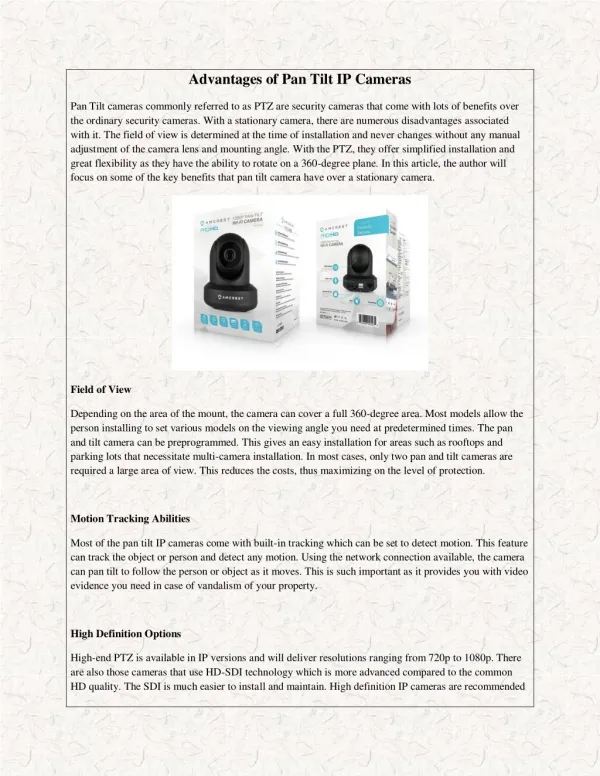
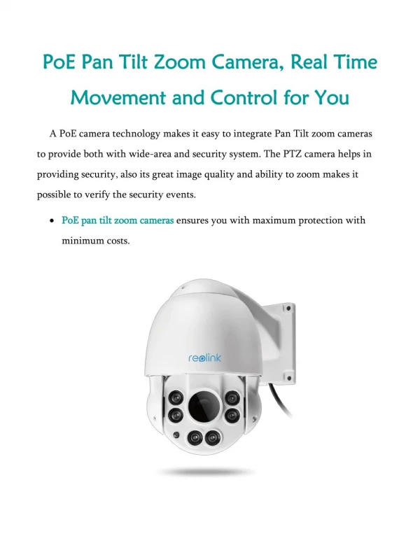
BACKGROUND • Fixed camera was used previously that will be replaced by tilt pan system. • Zooming was controlled mechanically by moving zooming button on the camera. It was unreliable, unsafe and insufficient. It will be replaced by digital system.
AIM To generate control signals for Tilt Pan movement and zooming of the camera on the UAV. Receive GPS data and camera position from control station and transmit camera control signals to control station via LAN. Display video along with approximate target coordinates using Tilt, Pan angles and GPS data.
SOFTWARE ANALYSIS • Control signals. • Joystick and keyboard. • Camera control. • Target coordinate calculation. • Transmission an reception via LAN. • Video display.
CAMERA CONTROL SIGNALS(TILT-PAN) • Clockwise pan rotation. • Counter clockwise pan rotation. • Stay pan. • Positive tilt(Towards nose). • Negative tilt(Towards tail). • Stay tilt. • Zero position. • Horizon.
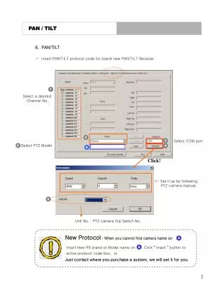
TEST OF SIGNALS FOR ZOOMING • Uses serial port connection and VISCA protocol to control various properties. • Demonstrate that camera can be controlled by any software that conforms to VISCA protocol. • Selection of signals that requires minimum transmission between ground and airborne stations. • Using same logic, program the micro controller in the UAV to control zooming.
USING VISCA PROTOCOL • Computer is called controller, camera is called peripheral device. • Parameters(speed=9600 bps, data bits=8, start bit=1, stop bit=1, no parity, MSB first). • Uses MS Comm control in Visual Basic for transmission of commands through serial port. • Takes control of the camera by sending two commands. 1. Address command 2. IF_CLEAR command
CAMERA CONTROL SIGNALS(ZOOMING) • Idle • Zoom in • Zoom out • Stop zoom • Full zoom in • Full zoom out • Zoom in speed(0 to 7) • Zoom out speed(0 to 7) • Digital zoom(ON or OFF)
THE PROTOCOL Protocol conforms to GPS NMEA 0183 code. • 1 2 3 4 5 6 $CMUAV,X,X,X,X,X,X 1) TILT (0=Zero, 1=Horizon, 2=Up, 3=Down, 4=Stay). 2) PAN (0=Zero, 1=Horizon, 2=Left, 3=Right, 4=Stay). 3) ZOOMING (0=Idle, 1=Zoom Out, 2=Zoom In, 3=Stop Zoom, 4=Full Zoom In, 5=Full Zoom Out).
THE PROTOCOL(Cont.) 4) ZOOM IN SPEED (0 to 7). 5) ZOOM OUT (0 to 7). 6) DIGITAL ZOOM(0=On, 1= Off).
JOYSTICK AND KEYBOARD • Visual Basic have been used for programming. • DLLs(Dynamic Link Libraries) of Windows API have been used for both joystick and keyboard programming. 1. A DLL is a library of functions that your program can link with dynamically. 2. We only need to know how to use a DLL and what functions it provides.
JOYSTICK AND KEYBOARD(Contd.) • Joystick uses winmm.dll (Windows Multimedia Dynamic Link Library). It gives status of the joystick and its current state. • Keyboard uses user32.dll (Library for user interface routines). It is used to find the current state of the keyboard as which key is pressed.
CAMERACONTROL • Joystick input has the priority over the keyboard. • Application can run with using only keyboard. • Application will continue even joystick gets disconnected.
TARGET COORDINATE CALCULATION Target coordinates have been calculated using these steps. • GPS gives the coordinates (latitude and longitude) of starting position. • Net azimuth is calculated by summing azimuth of the UAV and pan angle (angle made with nose of UAV). • Altitude above ground level is calculated by subtracting local height from AMSL(GPS).
Contd. • Distance from the starting position is calculated using AGL and tilt angle. • Distance is converted into angle made at center of the earth. • From the starting position, azimuth and distance angle the target coordinates are calculated. Algorithm has been derived from Mapping Toolbox of MATLAB and calculation from Visual Basic and MATLAB matches.
USING LAN • Winsock control from Visual Basic has been used. • Camera station acts as a client. • Control Station acts as a server and it must be available before the start of the application. • Camera station sends the camera control signals to the control station. • It receives GPS data and camera position information from the control station.
VIDEO • It uses ezvidcap control to grab and display video. • It just grab the video available in video grabber card and displays it.
ACHIEVEMENTS • Generated control signals using keyboard and joystick. • Ground based test of zooming properties of the camera. • Displayed the video captured along with its approximate coordinates.
RECOMENDATIONS • If laser altimeter is installed in direction of the camera, the coordinates calculated will be more accurate. • Course on Window based programming should be introduced. • Internet should be available during project phase.