Download
1 / 25
250 likes | 423 Views
The physics of RFID. Matt Reynolds Founding Partner ThingMagic LLC. Overview. A brief history of RFID Elements of an RFID system An ideal tag model and practical constraints An ideal reader model and practical constraints The basics of radio frequency propagation

E N D
The physics of RFID Matt Reynolds Founding Partner ThingMagic LLC
Overview • A brief history of RFID • Elements of an RFID system • An ideal tag model and practical constraints • An ideal reader model and practical constraints • The basics of radio frequency propagation • The basics of RF interaction with materials • Conclusions
1862 1886 1942 1948 1972 2003 printing lasers IC / VLSI networking supply chain scaling A brief history of RFID
Elements of an RFID system What is an RFID Reader? (eg Savant) Four main elements: Tags, Readers, Antennas, and Network Systems
RF system variables • Choice of operating frequency • Tag IC, tag antenna design • Reader, reader antenna design • Proximate materials • Sources of external interference
Major RFID markets by frequency US, Canada 125KHz 13.56MHz 902-928MHz EU Countries 125KHz 13.56MHz 868-870MHz Japan 125KHz 13.56MHz 950-956MHz
125 KHz TI Philips Others 13.56 MHz Tagsys Philips TI Microchip Others 915 MHz Intermec SCS Matrics Alien Philips TI 2.4 GHz Intermec SCS Hitachi RFID tags at different frequencies
Substrate Die attach Tag IC Antenna Tag anatomy
Tag block diagram Antenna Power Supply Memory Cells Control Logic (Finite State machine) Tx Modulator Rx Demodulator Tag Integrated Circuit (IC)
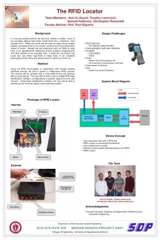
What does a reader do? • Primary functions: • Remotely power tags • Establish a bidirectional data link • Inventory tags, filter results • Communicate with networked server(s)
Reader anatomy Digital Signal Processor (DSP) Network Processor Power Supply 13.56MHz Radio 915MHz Radio
Reader block diagram rx data antenna Subsystem Band 1 Band Module Band 1 tx control rx data data antenna Subsystem Band 2 network processor Band Module Band 2 dsp subsystem TCP/IP tx control control rx data antenna Subsystem Band n Band Module Band n tx control
UHF (915MHz) reader RF section 915MHz band module schematic
A passive RFID communication model Reader Antenna Power from RF field Reader->Tag Commands Reader Tag->Reader Responses Tags RFID Communication Channel
Limiting factors for passive RFID Reader transmitter power Pr (Gov’t. limited) Reader receiver sensitivity Sr Reader antenna gain Gr (Gov’t. limited) Tag antenna gain Gt (Size limited) Power required at tag Pt (Silicon process limited) Tag modulator efficiency Et
Reader->Tag power transfer Reader Antenna Tag Reader Separation distance d Q: If a reader transmits Pr watts, how much power Pt does the tag receive at a separation distance d? A: It depends- UHF (915MHz) : Far field propagation : Pt 1/d2 HF (13.56MHz) : Inductive coupling : Pt 1/d6
Reader Transmit Power Pr = 30dBm (1 Watt) Reader Receiver Sensitivity Sr = -80dBm (10 -11 Watts) Reader Antenna Gain Gr = 6dBi Tag Power Requirement Pt = -10dBm (100 microwatts) Tag Antenna Gain Gt = 1dBi Tag Backscatter Efficiency Et = -20dB System operating wavelength = 33cm (915MHz) Typical UHF system parameters
Far field path loss Pt d Pr Pt = Pr • Gr • Gt •2 (4 π)2 d2
UHF read range estimation • Two cases: Tag power limited, or reader sensitivity limited. • Well designed systems are tag power limited. • Pt = Pr • Gr • Gt •2 • (4 π)2 d2 • dmax= sqrt ( Pr • Gr • Gt •2) • (4 π)2 Pt • dmax=5.8meters, theoretical maximum
Reader sensitivity limit • Let’s assume we can build a tag IC requiring 1 microwatt (100 times better than current practice) • dmax = 194 meters tag power limit for this hypothetical IC. Pt->r = Pr • Gr • Gt • Et • 2 • (4 π)2 d4 Pt->r =-99dBm Noise power in 50 ohm resistor at 500KHz BW=4kTB=-109dBm. With a practical receiver of NF=3dB, Pn=-106dBm, SNR=10dB. This signal is at the edge of decodability.
Lessons from the simple model • Since Pt 1/d2 , doubling read range requires 4X the transmitter power. • Larger antennas can help, but at the expense of larger physical size because G{t,r} Area. • More advanced CMOS process technology will help by reducing Pt. • At large distances, reader sensitivity limitations dominate.
RF signals and materials Materials in the RF field can have several effects: • Reflection / refraction • Absorption (loss) • Dielectric effects (detuning) • Complex propagation effects (photonic bandgap)
Effective shielding of UHF signals • Any conductive material exhibits a skin depth effect • = sqrt ( 2 / ( 2 f 0 ) ) where 0 = 4 x10 -7 H/m. For aluminum, = 2.65x10 -6 ohm-cm. An effective aluminum shield is only 27 microns thick. For dilute salt water, = 10 -2 ohm-cm. An effective salt water shield is 1 mm thick.
Conclusions • There are serious practical limitations to passive RFID read range. • It is not practical to read a passive UHF RFID tag from Earth orbit. • Improvements to tag IC design will yield commercially helpful, but probably privacy-insignificant increase in read range. • UHF RFID signals are easily shielded by common materials (aluminum foil, antistatic bags, or your hands).