Download
1 / 13
130 likes | 222 Views
GEO 600 detector status report (S4). K.A. Strain for the GEO 600 team. LSC Meeting LLO, March 2005 LIGO-G050094-00-Z. GEO600 optical layout (S4). 600m. Attenuated to 5W. interferometer with dual recycling. mode cleaners. 12W laser. ~1% Transmission. detector. Site (S4).

E N D
GEO600 detector status report (S4) K.A. Strain for the GEO600 team LSC Meeting LLO, March 2005 LIGO-G050094-00-Z
GEO600 optical layout (S4) 600m Attenuated to 5W interferometer with dual recycling mode cleaners 12W laser ~1% Transmission detector
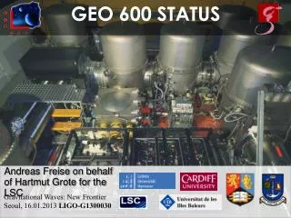
Site (S4) • Container-city grows
Progress (post S3 to preS4) • Improvements to michelson and signal recycling loops • less noise at low frequency through gain redistribution etc. • general reduction of RFI by improved signal handling • Substantial reduction of collimated-backscatter from several optics • most importantly those handling the “arm pick-off” beam used to obtain SR control signals (components repositioned or removed) • now normally no scattering problem • Modest increase in injected and circulating power (using almost half of the power from the 12W laser now) • 1 kHz performance limited by mixture of shot and dark noise
Progress (S3 to S4) • Noise projection work • all major linear contributions now tracked (control noise, amplitude noise, oscillator phase noise …) • some of the couplings tracked continuously to allow investigation of potential vetos • Calibration • full on-line calibration of the two instrumental output quadratures (“HP”, “HQ”) • remember detuned SR gives nearly SSB at response peak so nearly equal signal in P,Q. “HP” has more information <1 KHz, HQ > 1kHz • combination of HP and HQ signals to get h(t) • optimal signal recovery, some SNR increase
Progress (S3 to S4) • Computer / data exchange infrastructure • additional supervisory control computers • general upgrade of supervisory control computers to increase reliability, now very few problems • extension of on-site storage and various minor enhancements and upgrades of data handling computer infrastructure • rapid generation and publication of calibrated frames • many on-line monitors provided • summary reports generated
Sensitivity – Pre S4 example line: 150 Hz 200 Hz 250 Hz pump 820 Hz 32 violin modes +harmonics 4kHz RFI peak preliminary calibration
Continuous calibration • continuous injection of calibration lines • fitting of parameters (optical gain) to measured line amplitudes • sophisticated control model used to aid good fit • inverse filters calculated and applied to error point signals to produce HP and HQ • random error due to parameter miss-estimation is kept small • main uncertainty is systematic (overall gain) due to difficulty of establishing electrostatic drive response • long term plan to use separate calibration “actuator” • on-line calibration and good reliability allowed unattended frequent overnight runs
optical On-line optical TF measurements P and Q CAL actuator
Combining HP and HQ - example result • Resulting HQ’ contains almost no signal compared to HP’ -> h(t) • Noise cancels in some frequency regions, is uncorrelated in others
10 -21 10 -22 10 -23 10 1 2 3 10 10 10 Noise Projections - example Proj Det+shot -17 10 Proj FP-MCE-HV Proj FP-MCEI-MCNI Proj FP-MSR Proj MIC_VIS -18 10 Proj MID_VIS Proj Uncorr. Sum HP -19 10 -20 ASD [h/rt(Hz)] Frequency [Hz]
S4 • Pre S4: one fault developed <24 hours before S4 - fixed just in time • Early S4: intermittent fault in suspended EO modulator • reduced data quality for some times (part of some nights) about 10 bad periods of a few hours • problem identified and fixed • may (dis)qualify affected data where appropriate • duty cycle • many long lock stretches (up to >105s) • over 35 100% 8-hour shifts so far • only 2 shifts < 90% • two shifts (16hr /day) with experts on call (automated SMS calling 24/7)
Some next steps • Post S4 checks and calibrations • actuator calibration • checking vetos arising from noise projection work • Review of S4 after ~1 month • Exchange of T~1% MPR for one with T~1000 ppm • some changes to the control systems • will make acquisition more complex • increased thermal effect in BS may increase contrast defect, but we have modulation index capability to spare • currently contrast defect is ~10-6 • probably do not require OMC • Noise reduction and tuning to lower frequency to improve overlap with L1/H1/H2