Download

1 / 45
950 likes | 1.78k Views
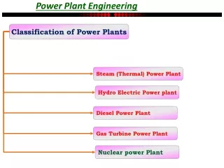
Implementation Of SCADA In Power Plant. Presented by Muhammad Usman tee-307-206. What Is SCADA?. SCADA stands for supervisory control and data acquisition . It generally refers to a computer system monitoring and controlling a process. Why SCADA is Needed.

E N D
Implementation Of SCADA In Power Plant Presented by Muhammad Usman tee-307-206
What Is SCADA? • SCADA stands for supervisory control and data acquisition. It generally refers to a computer system monitoring and controlling a process.
Why SCADA is Needed • Reduce the needs for field travel • Faster indication on field problems • Higher reliability of supply • Lower cost maintenance • Higher customer satisfaction • Reduce risk
Comm.- Basic SCADA System Structure • SCADA • HMI SCADA Modem PLC Versatile Interface Progr. Tool • Comm. • Interface • Progr. Tool • RTU • Local Control • Data Terminal • Local Display • RTU • Local Control
SCADA system has three layers • SCADA master • communication media • local control system
SCADA console The console is HMI SCADA server The server contains database for historical trends of relevant data. MTU (Master Terminal Unit). MTU is a terminal that communicates with RTU’s at local site. SCADA master consists of three main parts
Human Machine Interface (HMI) • This is the Heart of the System • Operator receives information via the HMI • System functions are initiated via the HMI • Architecture of the HMI • Single PC up to Hierarchical PC Network • Standby to assure reliability
Services of HMI Layer Wise • Higher Management • Information and Finance • Planning and Engineering • Mid Control Systems • Real time network management • Low Control System • Remote monitoring and Control • Alarm management
SCADA HMI Provides: • Monitoring of Parameters and Status • Pressures Flow Levels • Pump Operation status • Power consumption • Control of remote sites • Pump operation • Dynamic pressure control • Historical data collection and analysis • Trending on past demand and parameters • Fault events
Communication media • For the data communication between MTU and RTU, communication media will be chosen from • leased line • microwave radio • fiber optic transmission • satellite communication • Redundant Source for back-up
What is protocol? A protocol is a set of rules that governs how message containing data and control information are assembled at a source for their transmission across the network and then dissembled when they reach their destination. • IEC 60850-5-101 • IEC 60850-5-103 • DNP3 • Elcom-90 • TCP/IP and SLIP • ABB - RP570/571 • ABB - INDACTIC 2033 • GI74 • TG709/E & TG809
Site 2 Site 1 RTU RTU RTU RTU Remote Programming SCADA Data Communication Network
Remote Terminal Units An RTU converts the electrical signals from the equipment to digital values such as the open/closed status for a switch, Valve or pump etc. By sending and receiving these electrical signal RTU can control equipment. Reliable and Secure • Very Low Failure rate • Secure and Reliable messages • Expandable and Upgradeable • Provides platform for growth and enhancement • Modular concept allows simple modifications • Friendly to Operate and Maintain
What to Look for in a SCADA-RTU • Sufficient capacity to support the equipment at your site • Rugged construction • Secure, redundant power supply. • Redundant communication ports. • NVRAM • Watchdog timer • Intelligent control.
Housing & Chassis Power Supply CPU Frames I/O Modules Radios Software Remote Terminal Units
Antenna Optional Solar Panel Q RTU Monitor and Control Flow Dynamic Pressure Control
Pressure / flow Sensors Pump Power Main valve Start/Stop Controls Power Consumption Reduction 1/2
Case Study CRITICAL CONTROL Of BOILER
Manual Control • Human Errors • Hard Wired Logic Control (Contactors & relay's together with timers and counters) • Bulky and complex wiring • The work can be started only when the task is fully defined and this leads to longer project time.
Scada Environment Advantages • Reduced Space • Higher productivity • Superior quality of end product • Efficient usage of raw materials and Energy • Easy trouble shooting • Improved safety in working condition • Reduce Human Error
CRITICAL CONTROL PARAMETERS IN BOILER Level Control • Steam Drum level • De-aerator level Pressure Control • Steam pressure • drum pressure • De-aerator pressure • Turbine inlet pressure
Flow Control • Air flow • Steam flow • Water flow • Temperature Control • De-aerator temperature • Steam drum temperature • Turbine inlet steam temperature • Flue gas temperature
Purpose of PLC works ? Basics of a PLC function are continual scanning of a program. The scanning process involves three basic steps. • Testing input status • Programming execution • Checking and Correcting of output status Scanning time = Time for performing step 1+ Time for performing step 2+ Time for performing step 3.
PLC Working At the beginning of each cycle the CPU brings in all the field input signals from the input signals and store into internal memory of CPU is called as process input image (PII). User program will be available in CPU program memory. Once PII is read, CPU pointer moves in ladder program from left to right and from top to bottom. CPU takes status of input from PII and user program. The result of scan is stored in the internal memory of CPU called process output image or POI and Is sent to the field control.
I/O driver (SCADA) picks up PII and POI and transfers the image to database and this image is called driver image. This driver image available in SCADA database is used for graphical view of process monitoring from operator station (OS) in the central control room.