Download
1 / 43
2.15k likes | 5.15k Views
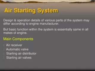
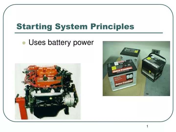
Starting System Principles. Uses battery power. AUTOMOTIVE STARTING SYSTEMS. Starter Circuit Electric DC Motor (starter motor) Solenoid or Relay Gear Drive Switches & Controls Wiring Testing Removing Starter. STARTING SYSTEM PARTS. Battery Ignition switch Solenoid Starting motor.

E N D
Starting System Principles • Uses battery power
AUTOMOTIVE STARTING SYSTEMS • Starter Circuit • Electric DC Motor (starter motor) • Solenoid or Relay • Gear Drive Switches & Controls • Wiring • Testing • Removing Starter
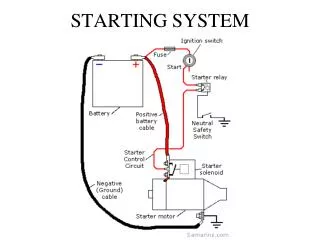
STARTING SYSTEM PARTS • Battery • Ignition switch • Solenoid • Starting motor
STARTER CIRCUIT • Battery / Cables • Magnetic Switches • Solenoids • Pull in Windings • Hold in Windings • Pinion Gear • Starter Relay
Starter Solenoid Functions • * Close battery to starter connection • * Push pinion gear into fly wheel • * Bypass the resistance wire of ignition circuit • Move the starter drive into mesh w. flywheel • Complete the starter circuit
Starting System Action • Turn key • Energizes solenoid • Current flows to Solenoid • 1 • Connects current to starter motor • Moves pinion forward • Turns starter • Motor turns flywheel • Turns crankshaft • Moves pistons up and down
Starter Motor Fundamentals • Converts Electrical Energy • From Battery • Into • Mechanical EnergyTORQUE
DC MOTOR • Basic Components • Housings and End Frames • Pole Shoes (magnets) • Field Coils • (windings) x 3 or 4 • Armature (spins) • Commutator • Brushes x4
MOTOR OPERATION • Magnetic Field Action • made of invisible lines of force (flux) • flow through wire • flow around wire • alike charges repel • Dissimilar Charges attract(spinning action) • Used to produce motion
DRIVE MECHANISM • Positive engagement • Movable pole shoe • Solenoid-actuated • Gear reduction drive
Simple Electric Motors • Wire loop field • Set up between poles • POLE SHOES
Changing Electricity Into Motion • Place windings inside pole shoes • Current through loop • Fields act upon each other
Commutators and Brushes • Used to keep motor spinning • by controlling current passing through windings commutator • Sliding electrical connection • Between motor windings and brushes • Many segments • Insulated from each other • Motor brushes • Ride on comutator • (slide on commutator) • Carry current to spinning windings
Commutators and Brushes • Increasing Motor Power • several windings • wires • Commutator • several segments • constant smooth motion
Armatures • Must produce HIGH torque • turning power • relatively high speed
Starter Armature parts • shaft • supports windings/armature • inside housing • Core (holds windings in place) • made of iron (Fe) • increases magnetic field strength • Commutator • for brush contact • Windings • wires
Field Windings • stationary insulated wires • wrapped in circular shape • creates strong magnetic field • around motor armature • 5-10 x stronger • than perminate magnets • field in pole shoes acts against field in armature • = motor spins
Pinion gear mechanism • Pinion gear • Clutch • Housing
Starter Pinion Gears • Small gear on armature shaft • Engages to flywheel • Meshes • Fly Wheel Turns Engine
Overrunning Clutch • Locks pinion gear in one direction • Releases it in other direction • Spiral grooves in shaft • Allows starter motor to crank the engine • Protects the starter from damage if the starter is cranked while the engine is running
Starter Solenoid • High current relay • Makes electrical connection between • Battery & starter • Electromagnetic switch • Handle VERY HIGH currents
Starter Solenoid Operation • Key turned (start position) • Current flows through solenoids windings • Produces magnetic field • Pulls plunger and disc into coil windings • Causes disc to touch both high current terminals • Completes circuit battery to starter • Current of 150-200A
Key Released • Current disconnected • Magnetic field collapses • Plunger slides back • Starter shuts off
Increasing Motor Power • Several windings • Wires • Comutator • Several segments • Constant smooth motion
RELATED MOTOR TERMINOLOGY • Left hand or right hand rule • Torque • Current Draw
STARTER DRIVE END • Connects the armature shaft to the flywheel. • Usually shifted out by the solenoid. • Contains an over- running clutch for protection. • Pinion gear meshes with the flywheel ring gear. • Returned to the rest position by a spring.
SOLENOID • A linear motor • Contains two windings a pull-in and a hold-in winding. • Pushes the starter drive(pinion) into mesh with the flywheel ring gear. • Completes the circuit to the motor.
CONTROL CIRCUIT • Starting Safety Switch • Neutral Safety Switch • On transmission • On Clutch
Starting Motor Types • classified by: • kind of pinion gear engagement • moveable pole shoe solenoid • Movable pole shoe uses a yoke “Y” • moves pinion gear hinged shoe on starter frame • yoke links pole shoe & pinion gear
Internal Motor Circuits • 3 common internal connections • Series • maximum torque • torque decreases throughout cranking • Shunt • Less torque • More constant torque • Compound • series/shunt • good toque • constant speed
Neutral Safety Switch • prevents cranking • unless in P or N • Ford - brake on • LOCATION • Connected in series with the ignition switch and solenoid • shifter or transmission
Starter Relay • Uses small current to control • a LARGERcurrent • Computer controls circuit (mV)
Starter Types • Starter Mounted Solenoids • plunger moves shift lever • GM/Chrysler • Permanent Magnet Starter • Use high strength permanent magnets • NOT CONVENTIONAL WINDINGS • = MORE torque
Starter Motor Torque • Must turn engine all components • Can Not Stall • Reduction starter • extra set of gears • increase rotating force • higher speeds • higher torque • more constant cranking speeds
Preliminary Tests Safety Precautions Troubleshooting Procedures Battery Load Test Cranking Voltage Test Cranking Current Test Insulated Resistance Test Starter Relay By-pass Test Ground Circuit Resistance Test Voltage Drop to Control Unit Test Components STARTER TESTING
Problems • Starter relay or solenoid clicks • low battery charge • Whining • Plunger stuck • Grinding • Poor engagement • Slow turn • Low battery • Internal short
Battery Load Test • VAT 40 • All Accessories on • ½ CCA
Test • Cranking Voltage • DVOM across battery • Cranking Current Test • Inductive Pick Up • Current draw • 150-200 AMPS • Voltage Drop Test
Tests • Test Relay • Ground Circuit Resistance Test • Starter Relay Bypass Test • Ground test • Bench test