Download
1 / 11
110 likes | 216 Views
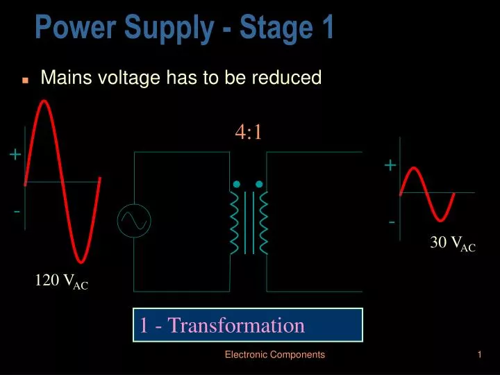
Power Supply - Stage 1. Mains voltage has to be reduced. 4:1. +. +. -. -. 30 V AC. 120 V AC. 1 - Transformation. Power Supply - Stage 2. Alternating voltage has to be converted to DC. 30 V AC. 9.6 V DC. Load. Half wave rectification. 2 - Rectification. Power Supply - Stage 2.

E N D
Power Supply - Stage 1 • Mains voltage has to be reduced 4:1 + + - - 30 VAC 120 VAC 1 - Transformation Electronic Components
Power Supply - Stage 2 • Alternating voltage has to be converted to DC 30 VAC 9.6 VDC Load Half wave rectification 2 - Rectification Electronic Components
Power Supply - Stage 2 • Alternating voltage has to be converted to DC 30 VAC -9.6 VDC Load Half wave rectification 2 - Rectification Electronic Components
Power Supply - Stage 2 19.1 VDC • Alternating voltage has to be converted to DC 30 VAC Full wave rectification RL 2 - Rectification Electronic Components
Power Supply - Stage 3 • Fluctuating voltage has to be smoothed RL RL = 5.1 k C = 33 F Vout = 40VDC with 1V ripple 3 - Filtered Electronic Components
Power Supply - Stage 3 (Filtering) When first turned on capacitor acts as a short. The surge current can damage diodes. This can be reduced by adding a surge resistor. RL RS Electronic Components
Power Supply - Stage 3 (Filtering) A more effective (although more costly) way is to use an inductor to oppose the changes in current. The capacitors in the LC filter oppose changes in voltage. RL Electronic Components
Power Supply - Stage 4 • Voltage has to be smoothed further RL Zener diode gives constant base voltage. Thus base current is constant and so will be the collector and emitter currents. 4 - Regulation Electronic Components
Graymark 808 Power Supply • Power supply was built from a kit. • Has two 0 - 15V and one 5V • Also has three protoboards • Ideal for doing analogue and digital lab projects Electronic Components
Graymark Power Supply Circuit Board • Bottom plate shows transformer and circuit board Bottom plate Transformer Electronic Components
Graymark Power Supply Filter capacitor IC regulator • Circuit board Rectifier diodes Electronic Components