Download
1 / 20
200 likes | 292 Views
Optical Fiber Calibration System and Adaptive Power Supply. Jiri Kvasnicka , Ivo Polak , Jaroslav Cvach Prague, Institute of Physics kvas@fzu.cz Gerald Eigen, Erik van der Kraaij PUniversity of Bergen ( UiB ), Norway. Introduction. The A nalogue H adron CAL orimeter

E N D
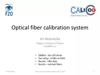
Optical Fiber Calibration System and Adaptive Power Supply Jiri Kvasnicka, Ivo Polak, JaroslavCvach Prague, Institute of Physicskvas@fzu.cz Gerald Eigen, Erik van der Kraaij PUniversity of Bergen (UiB), Norway LCWS 2013, November 11-15, Tokyo
Introduction • The Analogue Hadron CALorimeter • Physics prototype: 7608 channels with SiPMs • Ultimately: 8 millions of channels • Details see talk by Oskar Hartbrich • Challenge: calibration • short (<7ns) light pulses, tunable amplitude • Physics prototype • CMB (1 LED drives 19 optical fibers, 1 fiber illuminates 1 scintillator tile) • Engineering prototype • Integrated on HBU – 1 LED per 1 tile • External option – currently developed Quasi-resonant LED driver: QMB1A • Optical signal is transferred and distributed by the notched fibers • 3 fibers connected to 1 LED per • 1 notched optical fiber illuminates 24 scintillating tiles • Details on electronics perspective see my talk from last LCWS • Another task (AIDA): SiPM gain stabilization (ADApower board) • Electronic details will be shown. • Experimental results next talk by Gerald Eigen LCWS 2013, November 11-15, Tokyo
The LED driver – QMB1 QMB1 • Quasi-Resonant LED driver • Modular system • Dec 2012: QMB1a • External coil pads (for ~30 ns pulses) • New connectors, minor changes for higher repetition rates and shorter pulses • Boards are performing well • Performance measurements ongoing • Main parameters: • Smooth pulse shape (half-sine shape) • Variable amplitude (~1A peak) • Repetition rate up to 100 kHz • Fixed pulse width (2.4–3.5 ns) • PCB size 30 × 140 mm2 QMB1a LCWS 2013, November 11-15, Tokyo
Distribution of light: Notched fiber Illuminated by Green laser 24 notches • Plastic optical fiber, 1 mm in diameter • Light is emitted from the notches • The notch is a special scratch to the fiber, which reflects the light to the opposite direction • The size of the notch varies from the beginning to the end of the fiber to maintain homogeneity of the light emitted by the notches • Performance will be shown in this talk Emission from the fiber (side view) First notch Middle notch End position notch LCWS 2013, November 11-15, Tokyo
6-HBU setup • Full setup with 6 HBU (2.2 m of electronics!) • Data readout from all HBUs very stable • only 5 HBU equipped with tiles • 3 row of tiles (3×72 tiles) illuminated by notched fibers and QMB1 LED drivers • 1 row of tiles was illuminated by 1 QMB1 and 3 fibers (each fiber has 24 notches) fiber triplet bundle (see next slide) • SiPM biasing not fine tuned LCWS 2013, November 11-15, Tokyo
Notched fiber triplet • Why 3 fibers with 24 notches instead of 1 fiber with 72 notches? • 24 notches can be produced with better precision • The manufacturer has a semi-automatic machine for 24-notched fibers • Figure: light collection vs. 1mm fiber position • “Glued” manually by a TESA stickers • Stable for testing • Not usable for the production (it took us almost a day to install and de-install the fibers) 3mm LED 1mm fiber Align. pins PCB hole PCB hole LCWS 2013, November 11-15, Tokyo
Results Average SiPM response Good SPS fit range • 153 working tiles (90.5% of assembled tiles) • Gain was extracted from SPS, good fit with signal within 0.5–5 pixels range (noise-free channels even larger signal) • Gain extraction successful for 92% of the tiles within a single run • Some channels needed more light (especially tiles without holes in the PCB for the fiber) Average number of pixels hit Extracted pixel gain (from SPS) HG signal, QMB setting: 990,1030,1060 row Average optical signal (ADC/gain) [fired pixels] One of the best SPS Notch position LCWS 2013, November 11-15, Tokyo
Notched fiber performance Fiber triplet performance • First test with fiber triplets (2.2m total length) • Fiber prototypes used, which have quality issues (personal changes at manufacturer) • Light output along the fibers shown • Missing holes in the PCB (due to ASIC) clearly seen, but still got some light from reflection Row 1 SiPM response [pixels] No tiles Row 3 row No tiles No tiles Average optical signal [fired pixels] Notch position Notch position LCWS 2013, November 11-15, Tokyo No holes
Different measurements of the fiber Fiber performance (2) Normalized signal [-] • Fibers were measured: • During manufacturing • In our institute Lab • At DESY on HBU • We finally came to measurements agreement • Some troubles at the starting point (systematically lower, because fiber is lifted due to the connector) • Some points do not match (HBU vs. Lab) for unknown reason • For the fiber production, notches will have <15% spread limit Notch position Normalized signal [-] Fiber #42 No tiles Fiber #44 LCWS 2013, November 11-15, Tokyo Notch position
Adaptive Power Supply • The gain of SiPM depends on bias voltage and temperature • We want to keep gain constant adjust bias according to temperature • Goal: to build a regulator, that keeps the gain constant (<1%) • Linear slope 1 to 100mV/K (measured @CERN – see G. Eigen’s talk) • Designed for positive compensation slope (dV/dT), negative possible • Vout: 10 to 85 V • Analog feedback. Temp sensor has to be thermally coupled LCWS 2013, November 11-15, Tokyo
First ADApowertestboard HV part • Fully functional • Complete Results: see talk by Gerald LM35D temp sensor 10 mV/°C V Ref. 2m cable to temp. sensor Switches for configuration Slope & bias trimming Rough & fine OpAmps Temp monitor LCWS 2013, November 11-15, Tokyo
Results with the testboard 5 measurements at given temp With compensation Without compensation LCWS 2013, November 11-15, Tokyo
Summary • We have illuminated the full length of the 6-HBU setup by the LEDs • Setup worked smoothly and stable • First test of full length illumination (72 tiles) by a single LED and 3 notched fibers • Beautiful Single Pixel Spectra taken • Gain extracted for 92% of tiles in a single run • Some channels required more light for gain extraction (no holes in PCB, fiber lifted • SiPM saturation seen • Fiber to HBU gluing tuned • Good for tests • Not suitable for production – high assemble time • Adaptive power supply for SiPM was developed and tested • Functionality proven with the test circuit • Prototype is expected to be manufactured in December 2013 • Current phase – PCB design & components final selection and ordering LCWS 2013, November 11-15, Tokyo
Backup slides LCWS 2013, November 11-15, Tokyo
Saturation curves Row 1 • Each row: 3 fibers Row 3 Row 2 LCWS 2013, November 11-15, Tokyo
Saturation curves of row1 • B HBU 3 HBU 2 HBU 1 HBU 6 HBU 5 HBU 4 LCWS 2013, November 11-15, Tokyo
TESA Kleberpads fiber holder • B LCWS 2013, November 11-15, Tokyo
QMB1 optical power • Each UV LEDs has a slightly different threshold • Output power is not linear to the voltage settings LCWS 2013, November 11-15, Tokyo
Temperature sensor coupling LCWS 2013, November 11-15, Tokyo