Download
1 / 41
460 likes | 735 Views
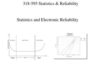
Implementation of Synchrophasor Technology for Better System Utilization & Reliability WAMS-WIDE AREA MEASUREMENT SYSTEM PMU-PHASOR MEASUREMENT UNIT. Need for Synchrophasor Technology. Visualisation of dynamic behaviour Stability aspects Operate the system at its limits

E N D
Implementation of Synchrophasor Technology for Better System Utilization & Reliability WAMS-WIDE AREA MEASUREMENT SYSTEMPMU-PHASOR MEASUREMENT UNIT
Need for Synchrophasor Technology • Visualisation of dynamic behaviour • Stability aspects • Operate the system at its limits • Protections backup & adaptive + adaptive islanding • State determination • Empower system operators
Phasor Representation A phasor is the complex form of the AC waveform √2Acos(2 πf t +ө) or Aejө or A< ө
Standards • The original standard for PMUs, C37.1344, was released in 1995 and was reaffirmed in 2001. • The new standard IEEE PC37.118 “Standard for Synchrophasors for Power Systems” has now replaced the earlier one. • There are no IEC standards at the moment and it is most likely that the IEEE will become IEC standard as was in the case of the COMTRADE standard.
Phasor Measurement Units A PMU by our convention measures bus voltage (phase or sequence) and all 3-phase line currents on all branches (transmission lines and transformers) emanating from the substation alongwith the phasor angles
FEATURES OF A PMU • TIME TAGGED AC PHASORS • +VE SEQUENCE VOLTAGES AND CURRENTS AS REAL & IMAGINERY QUANTITIES OR OUPUT AS MAGNITUDE & PHASE ANGLE FOR LOCAL & REMOTE APPLICATIONS • FREQUENCY & RATE OF CHANGE OF FREQUENCY • VARIABLE DATA TRANSFER RATES– 1 PER CYCLE, 1 PER 2CYCLES OR 1 PER 4CYCLES • SYNCHRONISED SAMPLING BY USE OF GPS- TIME TAGGING ACCURACY UPTO 50 µSECOND(GPS ACCURACY OF 1 µSECOND) • ACCURATE PHASE ANGLE CALCULATION WITH ACCURACY OF UPTO 1 DEGREE OR LESS
FEATURES OF A PMU-CONTINUED • CAN HANDLE 6 ANALOG CUURENT INPUTS WITH 3 ANALOG VOLTAGE INPUTS WITH OPTIONAL EXTENSION BY 100% • 2 SETTABLE LEVELS FOR FREQUENCY AND RATE OF CHANGE OF FREQUENCY • SETTABLE LEVELS FOR UNDER VOLTAGE & OVERCURRENT PICKUP • ONE ‘NO’ CONTACT FOR ABNORMAL FREQUENCY, RATE OF CHANGE OF FREQUENCY, UNDERVOLTAGE & OVERCURRENT PICKUP • LOSS OF DC AND OTHER INTERNAL SELF MONITORING
FEATURES OF A PMU-CONTINUED • REMOTE COMMUNICATION PORT FOR TCP/IP AND STREAMING DATA IN IEEE1344 OR PC 37.118 SYNCHROPHASOR FORMAT • OPTIONALLY ADDITIONAL OPTICAL COMMUNICATION PORT FOR TCP/IP AND STREAMING DATA IN IEEE1344 OR PC 37.118 SYNCHROPHASOR FORMAT • FRONT MOUNTED MENU DRIVEN DISPLAY FOR DISPLAYING +VE SEQUENCE VOLTAGE AND CURRENT AS AMPLITUDE AND PHASE ANGLE
Compute MW & MVAR Power P = V I cos(θ−φ) Reactive Power Q = V I sin(θ−φ)
Location 2 Location 1 Phase angular difference between the two can be determined if the two local clocks are synchronized. Synchronizing pulses obtained from GPS satellites. Synchronized Measurements
Role of GPS • Constellation of 24 satellites orbiting at 20,200 km • Developed by US dept of defense • Available for free for civilian use • Beyond navigation use, it provides time reference: • Protection systems derive usage of GPS from the timing signal • 4 satellites are needed for knowing timing and location position • Satellites have atomic clocks • Provides coordinated universal time (UTC) which is international atomic time compensated for leap seconds for slowing of earths rotations • can obtain accurate timing pulse every second with an accuracy of 1 microsecond
PMU Facts • PMU uses discrete Fourier transform (DFT) to obtain the fundamental frequency components of voltage / current(Half cycle or Full cycle) • Data samples are taken over one cycle / multiple cycles. • Currently, sampling is done at 12 samples/cycle (IEEE C37.111 Std.). • Resolution of the A / D converter is 16 bits.
Communication Options • Telephone lines • Fiber-optic cables • Satellites • Power lines • Microwave links
Delay Calculations…… • Fixed delay • Delay due to processing, DFT, multiplexing and data concentration • Independent of communication medium used • Estimated to be around 75 ms • Propagation delay • Function of the communication link and physical separation • Ranges from 25 ms in case of fiber-optic cables to 200 ms in case of low earth orbiting (LEO) satellites
Standards: Key Items • Time reference = UTC (Universal Time Coordinated) • Reporting rates = (10,25 phasors/sec for 50Hz system; 10,12,15,20,30 phasors/second for 60Hz system starting at the top of a second) • Optional reporting rates 50/100 phasors/sec for 50Hz and 60/120 phasors/sec for 60Hz. • Angle reference = cosine (0 deg at positive waveform peak) • Communication model (standard frames and data types, interoperability)
Hardware Requirements • Phasor Measurement Units (PMU) placed at strategic substations • Communication Links, including networking equipment at substations as well as at control centers • Phasor Data Concentrator (PDC) • Computer systems located at the central control centers, consisting of servers, storage, workstations and printing facilities.
Software Requirements • Phasor data collector software, for preprocessing of PMU data • Basic monitoring applications • Ergonomic graphical user interface, with results visualization facilities • Core power system application software; Analytics
Communications • Though many communication media is possible, fiber optic provides, by and large, the most secure and fast communication medium.
PMU placement It is not at all necessary to place PMUs at all busses in the power system to make it observable. When a PMU is placed at a bus, then it's neighbouring busses also become observable. In general, a system can be made observable by placement of PMUs on approximately 25% to 33% of the busses in the system Optimal PMU placement problem i.e., minimum PMU placement problem for system observability, can be formulated as an Integer Linear Programming (ILP) problem.
PMU placement 57 bus system
PMU Applications • SCADA Displays • State estimation • Control (WAMS)/SPS Measurement based controls for: Voltage Stability Angle Stability Frequency Stability • Event and system analysis • Improved operational observability • Dynamic System Stability Probe & Control - Power system damping-PSS • PMU data trends can detect CB/switch status changes in the network, which will improve the topology estimation
WAM Design Constraint < Computation time + Communication time Response time of the system dynamics
Opportunities Provided by WAMS • On-line or real time monitoring and state estimation • We can realize 1 state estimator run per cycle • provides us an opportunity to peep into electromechanical system dynamics in real time • upgrade from local control to wide area controller e.g., for PSS & damping controllers etc • improve performance of the apparatus protection schemes • improve performance of the system protection schemes • Accurate measurement of transmission system data in real time
WAM applications • Protection Power Swing blocking Improved back up protection Current Differential protection • Continuous Closed Loop Control ??? e.g., PSS using global signals Unfortunately: Require to accurately determine the communication latencies for continuous control
WAM applications Emergency Control (System Protection Schemes) • Controlled System Separation • Triggering of load shedding based on NON-LOCAL signals. Better df/dt relaying. • Triggering other schemes (generator shedding, dynamic brake, governor) etc. Some may require accurate loss of synchronism prediction
SPS: How can WAMS help ? • Angular instability : • Predict of out of step in real time -> trigger control actions like gen/load tripping or dynamic brake to prevent loss of synchronism. OR • Allow graceful system separation and do intelligent load/gen tripping to stabilize frequency and voltage in island Former is preferable - no resynchronization of systems required BUT how does one a) Predict out of step in real time b) Determine quantum of control actions For controlled system separation : Adaptive choice of separation points conceivable NON-LOCAL measurements may help
SPS: How can WAMS help ? • Frequency stability : Present day problems: • Local frequency contaminated due to swings (1 -2 Hz). df/dt should not trigger on swings but on “common” motion of generator speeds. Solution: filter, but filtering will involve delay. • Setting of df/dt relay should reflect actual power deficiency. Need to know total inertia (will need to know whether islanded or not, which generators in island) Conclusion : NON LOCAL signals will help!!
WAMS for Transmission Protection Systems • Current Differential Protection can be implemented with ease: • Most accurate • Provides crisp zone of protection • Free of non-idealities like tripping on power swings, non-tripping on voltage or current inversion, etc. • Can be applied to series compensated lines • Current Differential Scheme can be used to suitably block Zone-3 trips
B C A A Transmission System with a short line terminating into a long line WAM based Z3 Blocking • As Line BC is quite long in comparison to AB, Zone-3 on AB at A can trip on power swing • If Current Differential Protection was implemented on line BC, it could be used to block Zone-3 of relay AB if no fault is detected by it on BC • Since Z2 and Z3 timer setting are of the order of 15-30 cycles and 90 cycles respectively, communication delays will not be very critical • Blocking scheme will not impair but only improve the performance of the system
WAM Applications • Islanding Detection • Loss of Synchronism detection • Average line temperature can be estimated from true line impedance: picture of thermal overloading if it exists • Power System Restoration Better picture – better confidence level – better decisions. More remote actions
Roadmap on improving existing transmission system utilization • Provide better analytics to ISO/TSO to estimate line and system loadability • Use WAMS to improve performance of system protection schemes • WAMS based Out of step protection schemes • WAMS based islanding schemes (smart islanding) • Use WAMS to improve security of the existing transmission system protection schemes (smart protection)
Initiative in WR • Project under New Millennium India Technology Leadership Initiative • Along with POWERGRID, other members of the consortium are – • TCS • IIT Bombay • Tata Power
Implementation of WR Project • Part-I : Installation of PMUs and PDCs • Data collection at PDC level and visualisation • Part-II : Optimal placment of PMUs • State Estimator based on PMU data • System wide protection schemes • Supervised Zone-3 blocking schemes • Emergency control schemes • Parameter validation
Implementation of WR Project (contd) • Project duration: 3 years • 2 years for implementation and 1 year for testing • Expert guidance from Prof. A.G. Phadke of Virginia Tech • Total cost : 16.75 Cr + 2.21 Cr for making data available at SLDCs
Project Initiatives for NR • Number of PMUs – 4 ; with PDC at NRLDC • PMUs to be installed at Vindhyachal, Kanpur, Dadri and Moga • Total project cost : 3 Cr. • Implementation period : 3 months • Order placed on SEL