Download
1 / 59
590 likes | 732 Views
Lect # 1 Binary Systems. Digital vs. Analog. Analog – a continuous range of values Digital – a discrete set of values Like money Can’t get smaller than cents Typically also has maximum value. Benefits of using digital. Digital signal. Analog signal. Cheap electronic circuits

E N D
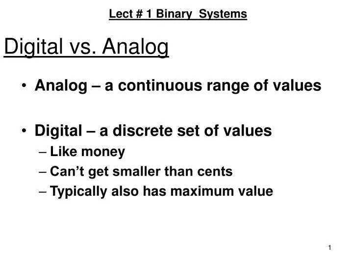
Lect # 1 Binary Systems Digital vs. Analog • Analog – a continuous range of values • Digital – a discrete set of values • Like money • Can’t get smaller than cents • Typically also has maximum value
Benefits of using digital Digital signal Analog signal • Cheap electronic circuits • Easier to calibrate and adjust • Resistance to noise: Clearer picture and sound
DIGITAL SYSTEMS • discrete information processing system • Discrete elements of info. are represented in a digital system by physical quantities called signals. • Electrical signals such as voltages and currents are the most common. • Digital systems that are constrained to take discrete values are further constrained to take binary values.
DIGITAL SYSTEMS Processor or Arithmetic Unit Control Unit Block Diagram of a Digital Computer Storage or Memory Unit Input Devices and Control Output Devices and Control
The memory unit stores programs as well as input, output, and intermediate data. The processor unit performs arithmetic and other data-processing tasks as specified by a program. The control unit supervises the flow of information between the various units. It retrieves the instructions 1 by 1, from the program which is stored in memory. For each instruction, it informs the processor to execute the operation specified by the instruction. Both program and data are stored in memory. The control unit supervises the program instructions, and the processor manipulates the data as specified by the program. The program and data prepared by the user are transferred into the memory unit by means of an input device. An output device receives the result of the computations and the printed results are presented to the user. The input and output devices are special digital systems driven by electromechanical parts and controlled by electronic digital circuits.
DIGITAL SYSTEMS • An electronic calculator is a digital system similar to a digital computer, why? ANS. The input device being a keyboard; the output device a numerical display; • *Instructions are entered by means of the function keys such as + and -; • Results are displayed directly in numeric form • A digital computer, however, is a more powerful device than a calculator, how? ANS. A digital computer can accommodate many other input and output devices; • it can perform not only arithmetic computations but logical operations as well
it can be programmed to make decisions based on internal • and external conditions • A processor when combined with the control unit, forms a component referred to as a central processing unit or CPU • A CPU enclosed in a small IC package is called a microprocessor • A CPU combined with memory and interface control to form a small-size computer is called a microcomputer
Binary System • Discrete elements of information are represented with bits called binary codes. • Example: (09)10 = (1001)2 • (15)10 = (1111)2 • Question: Why are commercial products made with digital circuits as opposed to analog? • Most digital devices are programmable: By changing the program in the device, the same underlying hardware can be used for many different applications.
MSD LSD Binary Code Review the decimal number system. Base (Radix) is 10 - symbols (0,1, . . 9) Digits For Numbers > 9, add more significant digits in position to the left, e.g. 19>9. Each position carries a weight. Weights: • If we were to write 1936.25 using a power series expansion and base 10 arithmetic:
Octal/Hex number systems The octal number system [from Greek: OKTW]. • Its base is 8 eight digits 0, 1, 2, 3, 4, 5, 6, 7 • (236.4)8 = (158.5)10 The hexadecimal number system. • Its base is 16 first 10 digits are borrowed from the • decimal system and the letters A, B, C, D, E, F are used for • the digits 10, 11, 12, 13, 14, 15 • (D63FA)16 = (877562)10
Conversion from Decimal to Binary • Find the binary equivalent of 37. 1 = 18 + 0.5 LSB 0 = 9 + 0 1 = 4 + 0.5 0 = 2 + 0 0 = 1 + 0 MSB 1 = 0 + 0.5 ? ANS:
Conversion from Decimal to Octal Conversion from decimal to octal: The decimal number is first divided by 8. The remainder is the LSB. The quotient is then divide by 8 and the remainder is the next significant bit and so on. • Convert 1122 to octal. LSB MSB
Conversion from Decimal to Octal • Convert (0.3152)10 to octal (give answer to 4 digits). 0.3152 x 8 = 2 + 0.5216 a-1 = 2 0.5216 x 8 = 4 + 0.1728 a-2 = 4 0.1728 x 8 = 1 + 0.3824 a-3 = 1 0.3824 x 8 = 3 + 0.0592 a-4 = 3 (1122.3152)10 = ( ? )8
00 01 02 03 04 05 06 07 10 11 12 13 14 15 16 17 Octal Table 1-2 page: 8
Conversion using Table Conversion from and to binary, octal, and hexadecimal plays and important part in digital computers. since and each octal digit corresponds to 3 binary digits and each hexa digit corresponds to 4 binary digits. • (010 111 100 . 001 011 000)2 = (274.130)8 • (0110 1111 1101 . 0001 0011 0100)2 = (6FD.134)16 from table
Complements Complements: They are used in digital computers for subtraction operation and for logic manipulation. Decimal Numbers 10’s complement and 9’s complement Binary Numbers 2’s complement and 1’s complement 9’s complement of N = (10n-1) – N (N is a decimal #) 10’s complement of N = 10n– N (N is a decimal #) 1’s complement of N = (2n-1) – N (N is a binary #) 1’s complement can be formed by changing 1’s to 0’s and 0’s to 1’s 2’s complement of a number is obtained by leaving all least significant 0’s and the first 1 unchanged, and replacing 1’s with 0’s and 0’s with 1 in all higher significant digits.
Complements 9’s complement of N = (10n-1) – N (N is a decimal #) • The 9’s complement of 12345 = (105 – 1) – 12345 = 87654 • The 9’s complement of 012345 = (106 – 1) – 012345 = 987654 10’s complement of N = [(10n – 1) – N] + 1(N is a decimal #) • The 10’s complement of 739821 = 106– 739821 = 260179 • The 10’s complement of 2500 = 104 – 2500 = 7500 Find the 9’s and 10’s-complement of 00000000 ANS: 99999999 and 00000000
1’s and 2’s Complements 1’s complement of N = (2n-1) – N (N is a binary #) 1’s complement can be formed by changing 1’s to 0’s and 0’s to 1’s 2’s complement of a number is obtained by leaving all least significant 0’s and the first 1 unchanged, and replacing 1’s with 0’s and 0’s with 1 in all higher significant digits. • The 1’s complement of 1101011 = 0010100 • The 2’s complement of 0110111 = 1001001 Find the 1’s and 2’s-complement of 10000000 Answer: 01111111 and 10000000
COMPLEMENTS Comparison between 1’s and 2’s Complements • 1’s complement • easier to implement by digital components since the only thing that must be done is to change 0’s to 1’s and 1’s into 0’s. • 2’s complement • may be obtained in two ways: • (1) By adding 1 to the least significant digit of the 1’s complement
COMPLEMENTS Comparison between 1’s and 2’s Complements • 2’s complement (2) by leaving all leading 0’s in the least significant positions and the first 1 unchanged, and only then changing all 1’s into 0’s and all 0’s into 1’s. • During subtraction of two numbers by complements, the 2’s complement is advantageous • only one arithmetic addition operation is required
COMPLEMENTS Comparison between 1’s and 2’s Complements • 1’s complement - requires two arithmetic additions when an end-around carry occurs. • 1’s complement has the additional disadvantage of possessing two arithmetic zeros: one w/ all 0’s and one w/ all 1’s.
COMPLEMENTS Comparison between 1’s and 2’s Complements • Consider the subtraction of two equal binary numbers 1100-1100 = 0 • Using 1’s complement: 1100 + 0011 + 1111 • complement again to obtain –0000 • Using 2’s complement: • 1100 • + 0100 • + 0000
COMPLEMENTS Comparison between 1’s and 2’s Complements • While the 2’s complement has only one arithmetic zero, the 1’s complement zero can be positive or negative, which may complicate matters. • 1’s complement is also useful in logical manipulations, since the change of 1’s to 0’s and vice versa is equivalent to a logical inversion operation.
Subtraction Using Complements Subtraction with digital hardware using complements: • Subtraction of two n-digit unsigned numbers M – N • base r: • Add M to the r’s complement of N: M + (rn – N) • If MN, the sum will produce an end carry and is equal to rnthat can be discarded. The result is then M – N. • 3. If MN, the sum will not produce an end carry and is equal to rn – (N – M)
Decimal Subtraction using complements • Subtract 150 – 2100 using 10’s complement: M = 150 10’s complement of N = + 7900 Sum = 8050 There’s no end carry negative Answer: – (10’s complement of 8050) = – 1950 • Subtract 7188 – 3049 using 10’s complement: M = 7188 10’s complement of N = + 6951 Sum = 14139 Discard end carry 104 = – 10000 Answer = 4139
Binary Subtraction using complements Binary subtraction is done using the same procedure. • Subtract 1010100 – 1000011 using 2’s complement: A = 1010100 2’s complement of B = + 0111101 Sum = 10010001 end carry Discard end carry = – 10000000 Answer = 0010001 Subtract 1000011 – 1010100 using 2’s complement: Answer = – 0010001
Binary Subtraction using complements • Subtract 1010100 – 1000011 using 1’s complement: A = 1010100 1’s complement of B = + 0111100 Sum = 10010000 End-around carry = + 1 Answer = 0010001 Subtract 1000011 – 1010100 using 1’s complement: Answer = – 0010001
Arithmetic addition Negative numbers must be initially in 2’s complement form and if the obtained sum is negative, it is in 2’s complement form. –6 11111010 +13 00001101 +7 00000111 + 6 00000110 +13 00001101 +19 00010011 Add –6 and –13 Answer = 11101101
BINARY CODES • Error-Detection Codes • Binary information, be it pulse-modulated signals or digital computer input or output, may be transmitted through some form of communication medium such as wires or radio waves. • Any external noise introduced into a physical communication medium changes bit values from 0 to 1 or vice versa. • An error-detection code can be used to detect errors during transmission. • The detected error cannot be corrected, but its presence is indicated.
Error-Detecting Code • To detect the error in data communication, an eighth bit is added to ASCII character to indicate its parity. • A parity bit is an extra bit included with a message to make the total number of 1’s either even or odd • The 8-bit characters included parity bits (with even parity) are transmitted to their destination. If the parity of received character is not even it means at least one bits has been changed.
BINARY CODES • A parity bit is an extra bit included w/ a message to make the total number of 1’s either odd or even. • During transfer of info. from one location to another, the parity bit is handled as follows: In the sending end, the message is applied to a “parity-generation” network where the required P bit is generated. • The message, including the parity bit, is transferred to its destination.
(a) Message P (odd) (b) Message P (even) 0000 1 0000 0 0001 0 0001 1 0010 0 0010 1 0011 1 0011 0 0100 0 0100 1 0101 1 0101 0 0110 1 0110 0 0111 0 0111 1 1000 0 1000 1 BINARY CODES PARITY-BIT GENERATION
1001 1 1001 0 1010 1 1010 0 1011 0 1011 1 1100 1 1100 0 1101 0 1101 1 1110 0 1110 1 1111 1 1111 0 BINARY CODES PARITY-BIT GENERATION
BINARY CODES • In the receiving end, all incoming bits are applied to a “parity-check” network to check the proper parity adopted. • An error is detected if the checked parity does not correspond to the adopted one. • The parity method detects the presence of one, three, or any odd combination of errors. • An even combination is undetectable. • Consider odd parity for a bit data 1111. • Received= 11111 (No error) • Received= 11110 (1-bit error detected) • Received= 11100 (2-bit error not detected) • Received= 11000 (3-bit error detected)
BINARY CODES • Reflected Code(also known as the Gray code) Digital systems can be designed to process data in discrete form only. Many physical systems supply continuous output data. These data must be converted into digital or discrete form before they are applied to a digital system. Advantage: A number in the reflected code changes by only one bit as it proceeds from one number to the next.
Reflected Code Decimal Equivalent 0000 0 0001 1 0011 2 0010 3 0110 4 0111 5 0101 6 0100 7 1100 8 BINARY CODES
1101 9 1111 10 1110 11 1010 12 1011 13 1001 14 1000 15
BINARY CODES • Alphanumeric Codes Many applications of digital computers require the handling of data that consist not only of numbers, but also of letters. An alphanumeric code is a binary code of a group of elements consisting of the 10 decimal digits, the 26 letters of the alphabet, and a certain number of special symbols such as $.
BINARY CODES • The total number of elements in an alphanumeric group is greater than 36. Therefore, it must be coded with a minimum of 6 bits (26 = 64, but 25 = 32 is insufficient). • One possible arrangement of a 6-bit alphanumeric code is shown in the table under the name “internal code.” The need to represent more than 64 characters gave rise to 7- and 8- bit alphanumeric codes. One such code is known as ASCII. Another is known as EBCDIC.
Character 6-Bit internal code 7-Bit ASCII code 8-Bit EBCDIC code 12-Bit card code A 010 001 100 0001 1100 0001 12,1 B 010 010 100 0010 1100 0010 12,2 C 010 011 100 0011 1100 0011 12,3 D 010 100 100 0100 1100 0100 12,4 E 010 101 100 0101 1100 0101 12,5 F 010 110 100 0110 1100 0110 12,6 G 010 111 100 0111 1100 0111 12,7 ALPHANUMERIC CHARACTER CODES
H 011 000 100 1000 1100 1000 12,8 I 011 001 100 1001 1100 1001 12,9 J 100 001 100 1010 1101 0001 11,1 K 100 010 100 1011 1101 0010 11,2 L 100 011 100 1100 1101 0011 11,3 M 100 100 100 1101 1101 0100 11,4 N 100 101 100 1110 1101 0101 11,5 O 100 110 100 1111 1101 0110 11,6 P 100 111 101 0000 1101 0111 11,7 ALPHANUMERIC CHARACTER CODES
Q 101 000 101 0001 1101 1000 11,8 R 101 001 101 0010 1101 1001 11,9 S 110 010 101 0011 1110 0010 0,2 T 110 011 101 0100 1110 0011 0,3 U 110 100 101 0101 1110 0100 0,4 V 110 101 101 0110 1110 0101 0,5 W 110 110 101 0111 1110 0110 0,6 X 110 111 101 1000 1110 0111 0,7 Y 111 000 101 1001 1110 1000 0,8 Z 111 001 101 1010 1110 1001 0,9
12-BIT CARD CODE When discrete info. is transferred through punch cards, the alphanumeric characters use a 12-bit binary code. • A punch card consists of 80 columns and 12 rows - in each column an alphanumeric character is represented by holes punched in the appropriate rows. A hole is sensed as a 1 and the absence of a hole is sensed as a 0. • The 12 rows are marked, starting from the top, as the 12, 11, 0, 1, 2,…,9 punch. The first 3 are called the zone punch and the last 9 are called the numeric punch.
The 12-bit card code is inefficient w/ respect to the number of bits used. BINARY CODES • Most computers translate the input code into an internal 6-bit code. As an example, the internal code representation of the name “John Doe” is: 100001 100110 011000 100101 110000 J O H N blank • 010100100110 010101 D O E
Binary Storage and Registers • Register is a group of binary cells that are responsible for storing and holding the binary information. • Register transfer operation is transferring binary operation from one set of registers to another set of registers. • Digital logic circuits process the binary information stored in the registers.