Download
1 / 18
180 likes | 329 Views
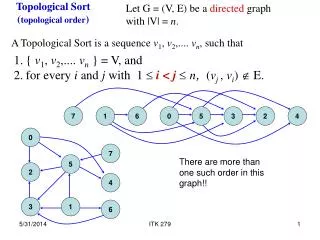
Phase-0 Topological P rocessor . Uli Schäfer Johannes Gutenberg- Universität Mainz. Topological Processor. S imulations suggest a need for topological trigger criteria, so as to keep Level-1 trigger effective at high luminosities. Example algorithms:

E N D
Phase-0 Topological Processor UliSchäfer Johannes Gutenberg-Universität Mainz
Topological Processor Simulations suggest a need for topological trigger criteria, so as to keep Level-1 trigger effective at high luminosities. Example algorithms: • Angular correlations (jets, direction of missing energy) • Muon isolation • … Hardware implementation Need to feed a maximum of data into a single point (module, FPGA) • Input from L1Calo and Muons • ~ 1 Tb/s aggregate bandwidth • Do not partition into multiple modules for reason of latency. TOPO
Current L1Calo Scheme • Mixed Signal Pre-Processor • FPGA based digital “sliding window” processors (e/m cluster, jet/energy) • Object count and global quantities via chained mergers CMM into CTP • Object positions to Level-2 and DAQ only 40Mb/s CTP PPr 480Mb/s analog real-time paths shown only CP JEP
Phase 0 Scheme • New CMX module with two interconnect options • Chained (legacy and opto links) • Star topology with all opto links into topological processor • Muon information included on topo processor TOPO Muon 6.4/10Gbps CTP PPr(nMCM) 480Mb/s analog real-time paths shown only CP JEP
… Topology Processor • Input from L1Calo and Muons • ~ 1 Tb/s aggregate bandwidth • Fibre optical inputs @ 6.4/10 Gbps per fibre • Output to CTP • electrical (LVDS) • fibre optical ~ 1Gb/s + • Interfaces to TTC/GBT/…, Level-2, DAQ, control, DCS,… • Small number of modules (~1) • Probably dedicated crate, near CTP Have started upgrade programme • 2010 : 6.4Gb/s data source BLT in CP/JEP cratesto live in CMM slots CMX • 2011 : Topo processor demonstrator GOLD 2013/14 topological processor commissioned in USA15
Phase-0 TopoProcessor floor plan front panel connectors Z3 opto Z3: opto connectors for real-time input 12-chan M Mezzanine connector Z2 Z2: electrical connectors • A / B FPGAs XC7VX690T-FFG1927 A B Power supply and control Z1 • AdvancedTCA322x280 mm
Bandwidth / Algorithms / Latency Baseline two FPGAs per processor 80 Links/FPGA @ 10Gb/s 1.6Tb/s total 1.28Tb/s payload Preliminary data formats for jet and cluster processors:96*(14*8+32) bit @40 MHz => 553Gb/s For muon data assume data volume comparable to current MUCTPI input: 8*13*32 bit @ 40MHZ =>134Gb/s Plus ε (energy, ?) Some level of data reduction on the CMX is being considered • One or two FPGAs per processor seem appropriate • Dependent on processing resources required for algorithms one might wish to duplicate processors • Forward link duplication for latency minimisation • Multiple processors on module • Multiple modules in crate
Algorithms Several algorithms have been suggested: • Jet dφ • Cluster dφ • Muon isolation • Muon MET • Jet/cluster overlap removal Some have been simulated and shown to be effective Algorithms require • Sorting of objects to size • Cuts in η,φ • Possiblycutsforabsenceofobjects in givenη,φ bin Choose reference algorithm and put in hardware !
Reference Algorithm • Define bandwidth requirements • Determine consumption of logic resources • Determine latency • Baseline device for Phase-0 topo processor is Virtex-7 • Target for reference algorithm implementation is Virtex-6 • Xilinx development board now - limitations in input channel count, link speed • GOLD topo demonstrator in a couple of months time • Choose an algorithm that has been physics-simulated in MZ and shown effective: Jet dφ
Jet dφ • Based on preliminary phase-0 JEP backplane data format • 32 JEMs × (4 jet candidates × 14 bits + 8 presence bits) 82Gb/s input bandwidth • Select two largest candidates in a 6-deep sort tree • Feed position information into lookup-table to allow for cuts in η and φ • Report single result bit to CTP First results on a XC6VLX240T: • 8 % of available CLB LUT resources used • 5 % of block memory resources used • Algorithm latency, down to the FPGA pin : 3 LHC bunch ticks But : mind the gap !
Latency Latency is actually dominated by the MGT links. Including that we arrive at a total latency : with buffered transmission scheme : 8 bunch tickswith phase alignment : 7 bunch Health warnings: • Latency figures are preliminary, working on reduction • Total latency comprises serialisation from 320Mb/s on CMX, de-serialisation to 40Mb/s on topology processor, and algorithm • Latencies have been calculated from data sheet, obtained from VHDL simulation, and been measured • Measured link latencies have been extrapolated from 3.2 Gb/s to 6.4Gb/s due to bit rate limitations on Xilinx development board • Different partitioning of the sort tree into CMX / topo processor will not affect algorithm latency • “phase alignment” low latency mode has been partially withdrawn / restricted by Xilinx for current devices (errata AR#39430) • Eventually we will want to target Virtex-7 and should therefore deal with Virtex-7 errata rather than Virtex-6 ones
“GOLD” demonstrator / medium term plans • (Full-function) demonstrator for phase-0 topology processor https://indico.cern.ch/getFile.py/access?contribId=19&sessionId=7&resId=2&materialId=slides&confId=112739 • ATCA format, modular, optical RTM connectivity @ 6.4 / 10Gbps • L1Calo internal review passed in May • PCB in production / assembly • From 08/’11 available for signal integrity and latency studies • Test bench for topology algorithms • Initial system tests with current L1Calo and CMX prototype • Review input connectivity requirements (including Muons) • Review processing power requirements (algorithm dependent) • Topology processor prototypes in 2011/12, baseline : Virtex-7 • Commission production modules in 2013/14 shutdown • Connect up with CMX and CTP • Connect up with muons as soon as muon trigger signals become available • . . .
The demonstrator : GOLD • Functional demonstrator for phase-0 topology processor • Technology demonstrator for technologies to be used throughout L1Calo upgrade programme, studies on fibre optical connectivity schemes -----> • ATCA form factor • Modular concept • Mezzanines • FMC connectors • Optical backplane connectors rather than front panel I/O • Opto/electrical conversion on input mezzanine • Electrical connectivity up to 10Gb/s in ATCA zone 2 • Phase-0 topo-specific connectivity • Provide all interfaces
GOLD floor plan A-J FPGAs A C front panel connectors Z3 Z3: opto connectors Mezzanines V E W B D Z2 V – Y : FMC connectors F X Z2: electrical connectors Y G H J Z1 • AdvancedTCA322x280 mm
GOLD - some details Main board, ATCA sized, 22 PCB layers • FPGAs (Virtex-6 LXT, HXT) • Connectors, sockets for e/o converters • FPGA configurator and local clocks (DAQ/ROI, Ethernet,…) • Main power distribution network (central and POL regulators) Input mezzanine module, allow for choice of input devices and input signal routing • 12 layers, moderate real estate • Sockets for o/e converters, 10Gb/s fanout Clock mezzanine module • Recover and condition incoming (LHC bunch) clocks • Some limited clock multiplexing and fan-out • Provide additional space for auxiliary components and front panel connectivity
GOLD floor plan • Z3 • 5 * XC6VLX (Processor L, main processor M) up to 36 links each • Two pairs of XC6VHX (H) 72 links each • 5+ 12-channel optos on daughter • Clock generation • 144 multigigabit input links in zone 2 (equiv. 22300 bit / BC) • L • L • Opto • M • L • L • H • H • Z2 • 890Gb/s • total • H • H • Z1