Download
1 / 24
240 likes | 245 Views
Qualification and Integration of the Laser Transmitter for the CALIPSO Aerosol Lidar Mission Floyd Hovis, Greg Witt, Ed Sullivan, and Khoa Le Fibertek, Inc Carl Weimer and Jeff Applegate Ball Aerospace & Technologies Corp. Presentation Overview. Programmatics

E N D
Qualification and Integration of the Laser Transmitter for the CALIPSO Aerosol Lidar Mission Floyd Hovis, Greg Witt, Ed Sullivan, and Khoa Le Fibertek, Inc Carl Weimer and Jeff Applegate Ball Aerospace & Technologies Corp.
Presentation Overview • Programmatics • Flow down of system level lidar requirements • Laser transmitter performance • Laser transmitter qualification • Lidar integration & test
Program Overview • Fibertek responsibilities • Design, build, and qualification of the laser transmitter • Support of post ship testing at Ball • Fibertek was supported by Ball in design and test issues unique to space-qualification • Radiation hardness • Electrical parts selection • Contamination control • Software qualification • Environmental testing • Ball responsibilities • Payload design, production, and integration • Rayleigh/ Mie Lidar for clouds and aerosols (CALIOP) • Wide Field Camera (modified startracker) • Imaging Infrared Radiometer (Sodern/CNES) • Joint development activities with NASA LaRC • Management and support of the laser transmitter contract to Fibertek • Payload Flight Software • Science Data Delivery System • X-band Transmitter and antenna • Ground Support Network (United Space Network) • Satellite integration and test support (at Alcatel in Cannes and Vandenberg Air Force Base) • On-Orbit Commissioning support
System Level Lidar Requirements • The lidar requirements were part of NASA’s SOW to Ball • Prior to starting the Flight Build, the Risk Reduction Laser (RRL) was completed • Demonstrated design approach for the laser and basic laser performance • RRL performance provided basis for lidar/ laser trades • An iterative approach to the lidar design produced the final requirements for the flight lasers.
Laser Transmitter Subsystem Performance Requirements Laser performance requirements are not particularly stressing from a laser design viewpoint • 1064 nm energy 100-125 mJ • 532 nm energy 100-125 mJ • Pulse width 15 ns < t < 50 ns • Repetition rate 20 Hz • Beam quality < 10 mm-mrad, both • 1064 nm line width < 150 pm • 532 nm line width < 35 pm • 532 nm polarization > 100:1 linear • Beam co-linearity < 10 % of output divergence • Beam jitter < 10 % of output divergence
Laser Transmitter Subsystem Performance Requirements System level requirements are more challenging • Lifetime of 2 billion shots • Pure conduction cooling • Fully redundant lasers and electronics • Modest thermal requirements • Operate within specification in a +/- 5°C band around optimum (~20°C) • Operate without damage from -5°C to 30°C • No impact from non-operational -30°C to +60°C thermal cycling • Power requirements are somewhat challenging • No more than 20 W required in standby • No more than 102 W required operationally • Severe vibrational requirements (>10.5 grms) • Dual wavelength energy monitors with +/-2% precision over full orbit • Based on integrating sphere technology • 100 urad +/- 10 urad final divergence required matched shimming of Beam Expander Optics to each laser • Electro-Magnetic Interference specification
System Level Lidar Requirements Lidar requirements determined the Flight Laser specifications Lidar RequirementImpacted Laser Specification Reliability Pump diode lifetime Canister leak rate Laser & electronics redundancy Contamination Control Plan/materials used Parts use for radiation (KTP, laser FETs) Lidar Stability (<4.7%)/orbit Energy Monitor Stability –Orbit/Orbit Pointing stability Wavelength stability Linewidth Efficiency Electrical power conversion efficiency Diode efficiency & spectral distribution Resonator efficiency Polarization 532 nm polarization purity & alignment An iterative process was used to develop a final set of laser specifications that allowed the lidar system requirements to be met
LEU LOM #1 LOM #2 Laser Transmitter Reliability • RRL demonstrated required 3 year, 2 billion shot lifetime • Each flight Laser Optics Module (LOM) had a dedicated set of electronics for full redundancy • A flight-like canister pressurized to 28 psia passed He leaks tests after qualification level vibration and during three –30°C to 70°C thermal/vacuum cycles • Both flight units passed helium leak testing during four –30°C to 60°C thermal/vacuum cycles before the beginning and at the end of qualification testing Fully redundant lasers and electronics Risk Reduction Laser Thermal vacuum helium leak testing of laser canister
0.015 LOM#1 0.010 LOM #2 0.005 5 Relative to Nominal (532.213nm) 0.000 4 -0.005 Energy Monitor Reading 1064 nm -0.010 3 532 nm -0.015 15 16 17 18 19 20 21 22 23 24 25 2 1 Raw reading (Volts) Convert to energy (mJ) 0 Average Min Max s Average Min Max s 0 100 200 300 400 500 600 700 800 900 1000 Time (seconds) 532 nm: 3.735 3.64 3.84 ± 0.031 112.8 109.2 116.9 ± 1.1 1064 nm: 4.034 3.96 4.12 ± 0.031 111.4 109.6 113.4 ± 0.7 Laser Stability • Energy monitor precision over full orbit 2% • Shot-to-shot energy jitter is 1.1% • 532 nm wavelength varies ~ 20 pm over a 10°C change • Value is consistent with the temperature shift of the Nd:YAG emission profile • Laser output energy unchanged since delivery in 2002 • > 99.5% of the of the pulses had pointing jitter that was <10% of the full beam divergence Pedestal Temperature (C) 532 nm wavelength vs. laser head temperature Shot-to-shot energies
RRL Efficiency Measurements 6 5 4 Efficiency (%) 3 2 1 0 0 5 0 1 0 0 1 5 0 2 0 0 2 5 0 Output Pulse Energy (mJ) Laser Efficiency • RRL measurements with the RRL show that higher efficiencies are achieved with higher pulse energies • Two key efficiency drivers: 1) electrical power conversion efficiency & 2) spectral overlap of diodes with Nd:YAG absorption bands • Electrical power conversion efficiency of 83% • Spectral overlap somewhat off peak due to requirement to match peak 532 nm etalon transmission • LOM 1 wall plug efficiency was 4.2% (4.4 W output for 104 W total electrical input) • LOM 2 wall plug efficiency was 4.4% (4.4 W output for 100 W total electrical input)
Laser #1 Laser #2 Laser #2 previous measurement (without BEO) Vector Orientation -2.1 mrad -16.8 mrad -16.6 mrad Extinction Ratio 1450:1 2860:1 ~3400:1 Extinction Stability Stable to < 4% once laser is at thermal equilibrium Y Y Z Z 532 nm Extinction Ratios After BEO Laser #2 Laser #1 Integrated Laser Polarization Measurements Summary of Extinction Ratios and Polarization Alignment • The 532 nm polarization ratios after the Beam Expander Optics meet the 1000:1 lidar requirement • Aligning the axis of the 532 nm polarizations to within a fewmrad of the axis of the alignment cube was a significant technical challenge • Thermal equilibrated polarization stability was < 4%
Module vibration and seal testing LOM & LEU qualification testing • Diode-pumped laser head burn in • Canister seal testing • Canister/optical bench vibration testing • Burn-in • Thermal/vac seal test • Vibration testing • Operational vacuum testing Laser Environmental Qualification A systematic approach to laser qualification, beginning at the optical subassembly level and proceeding incrementally to the full module level, has resulted in the successful qualification of both Laser Optic Modules as well as the Laser Electronics Unit Optical component and subassembly testing • Nd:YAG slab • Corner cube • Steering prism Telescope • Porro prism • Q-switch • Second harmonic generator • Diode arrays
Four –30°C to +60°C cycles 100 hour operational burn-in Bench/Canister Integration Thermal Cycling and Burn-In Baseline Performance Test Helium Fill Thermal Vacuum Seal Test Helium Purge Four –30°C to +60°C cycles Helium Fill Helium Purge Vibration Test Functional Test Thermal Vacuum Seal Test Operational Vacuum Test Acceptance Test Flight Laser Delivery Additional Thermal Characterization at Fibertek Laser Optics Module System Level Qualification Qualification Flow Plan Both laser's outputs were unchanged at the end of full space-qualification testing
Laser Build & Qualification Issues • Space-qualified electronics were more expensive to build and test than anticipated • Use of radiation hard parts required complete redesigns of previously used electronics • Laser Electronics Unit test plan required almost 2 man years of effort to develop • Software Flight Qualification Test was more extensive than originally planned to meet NASA requirements • Software test procedure alone was >70 pages and was executed 5 times • Conducted EMI due to pulsed power draw required addition of large EMI filter by Ball • Subtle power supply changes surfaced intermittent start up glitches after space craft integration and required modification to the Laser Control Board
Integrated Laser Transmitter (ILT) Laser Optic Modules (LOMs) Radiator Beam Expanding Optics (BEOs)
Integrated Laser Transmitter (ILT) Radiator Beam Expanding Optics (BEOs)
Laser Electronics Unit Radiator
Payload Integration Integrated Laser Transmitter
Spacecraft Integration Laser Electronics Unit
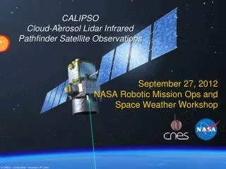
Orbital Laser Performance • CALIPSO launched on April 28, 2006 • Health of the electronics and internal pressure verified for both lasers ~ 2 weeks later • Laser #2 was successfully operated at full power on May 23 • Total power unchanged, small balancing of 1064 nm/532 nm needed • A lidar ground return was observed even though the laser transmitter assembly pointing had not been aligned, yet. • The laser was shutdown to allow final orbit correction maneuvers and was restarted June 6 after the satellite had entered the A-Train • Final laser and lidar alignments performed week of June 5 • First lidar data released June 9
Orbital Laser Energy Trend – First Day Laser firing at 20 Hz, energy data sampled at 0.2 Hz (one sample per 100 shots)
Orbital Energy Distribution- First Day Histogram and statistics computed after removing linear trend from chart above
Acknowledgements • We wish to acknowledge the support of Bill Luck, Chris Hostetler, and Alan Little at the NASA Langley Research Center; and Lyle Ruppert and Justin Spelman at Ball Aerospace & Technologies Corp. for their support in the generation and analysis of the data in this presentation