Download
1 / 30
300 likes | 304 Views
Machining compensation experiment – progress report. J.Huopana 28.5.2008. Main idea. CAD/CAM-softwares are used to design the geometry and the manufacturing Machining of the piece Measuring the machined surface.

E N D
Machining compensation experiment – progress report J.Huopana 28.5.2008
Main idea • CAD/CAM-softwares are used to design the geometry and the manufacturing • Machining of the piece • Measuring the machined surface • Results of the measurements are analyzed and the reasons for the errors determined. Based on these findings a new geometry will be created in the CAD/CAM environment to compensate the found errors. • A new piece will be machined • Result: better accuracy compared to the first
Toolbox Experience & ideas Mitutoyo Series 355 Euro Apex Strato 9166 X-axis range 905 mm Y-axis range 1605 mm Z-axis range 605 mm Resolution 0.0002 mm Accuracy 1.7 605 mm Resolution 0.0002 mm Accuracy 1.7 µm Hermle C30U +/- 3-5 µm
Toolbox Experience & ideas Mitutoyo Series 355 Euro Apex Strato 9166 X-axis range 905 mm Y-axis range 1605 mm Z-axis range 605 mm Resolution 0.0002 mm Accuracy 1.7 605 mm Resolution 0.0002 mm Accuracy 1.7 µm Hermle C30U Hermle C30U +/- 3-5 µm
CAD/CAM design Test piece • Shape has been extracted from VG1 (CLIAAS110001) • Green surfaces are designed for metrology • Shape tolerance goal better than +/- 5 µm • Modeled in CATIA and in MasterCAM
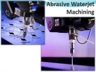
Machining • 5-axis machine • One axis is used to tilt the test piece to have more material to remove • After the tilting (5 deg), machining is 3-axis • the machine is stabilized (respectively) • Air condition, 6 hours of operation before starting the machining
Contact Measuring Machine • Five profile measurements • 45 deg profile (shape1) • Profile from the right (shape 2) • Profile from the left (shape 3) • 45 deg profile to the opposite direction (shape 4) • Profile from the bottom of the cell • (shape 5) Shape 4 Shape 5 Shape 1 Shape 2 Shape 3
Tests • 2 main strategies to machine the piece (surface) • Both were machined and measured to determine the ”right” method
Test piece 1 • surface quality, considering Ra 0,2, is not achievable with current cutting speed of 18000 rpm (not a goal in this study) • problematic connection of surfaces visible, might be possible to fix with changes in CAM • burrs visible, also possible to improve the situation by changing CAM-design
Test piece 2 -changes were made for the tooling directions and movement to have smoother surface in the iris area and to remove burrs -changes were made according the first test -a error of 6 µm visible in every shape => Tool length (0.006 mm)
What happens when you compensate to the wrong direction? This Test 3
What happens when you compensate to the wrong direction? This Test 3 MURPHY'S LAW §15. ”In an instrument or device characterized by a number of plus-or-minus errors, the total error will be the sum of all the errors adding in the same direction.”
Future work • Compensate the tool length • Compensate the bending of the piece • Measuring and verifying the effectiveness of the method