Download
1 / 17

E N D
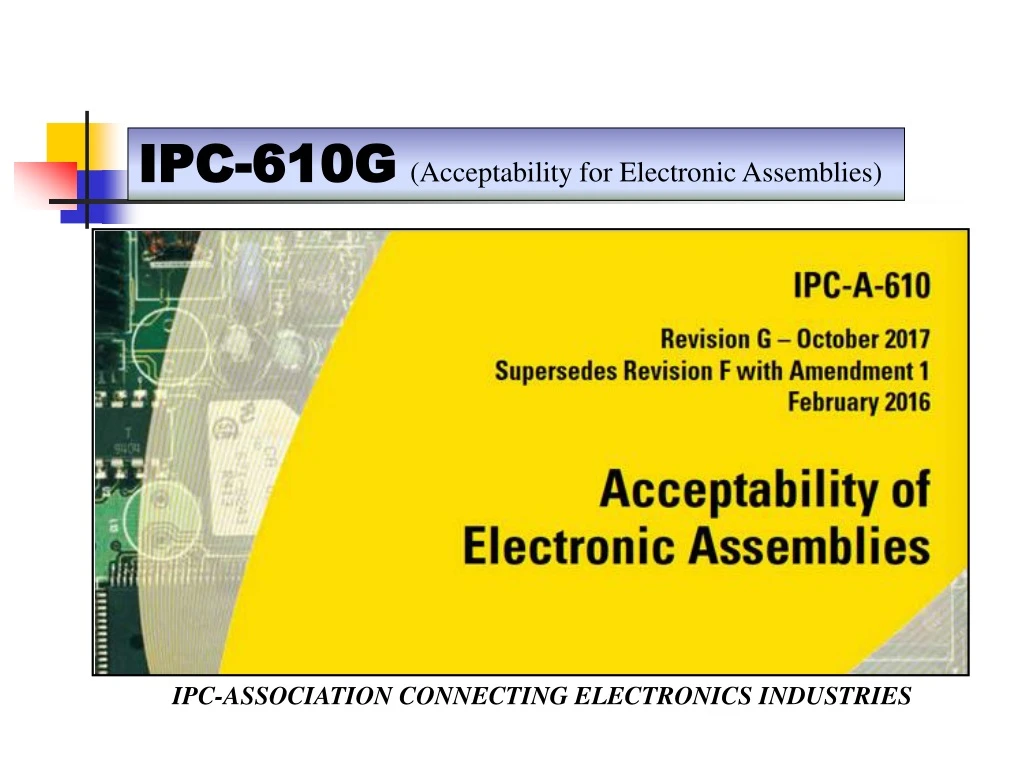
IPC-610G(Acceptability for Electronic Assemblies) IPC-ASSOCIATION CONNECTING ELECTRONICS INDUSTRIES
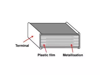
IPC-610G(Acceptability for Electronic Assemblies) Terminal :- A terminal is the point at which a conductor from a component , device or network comes to an end. Terminal may also refer to an electrical connector at this endpoint, acting as the reusable interface to a conductor and creating a point where external circuits can be connected. 6 Terminal Connections 6.1 Edge Clip
IPC-610G(Acceptability for Electronic Assemblies) 6.1 Edge Clip Target - Class 1,2,3 • Clip is centered on land with no side overhang. Acceptable - Class 1,2,3 • Clip has 25% maximum overhang off land. • Overhang does not reduce spacing below minimum electrical clearance. Defect - Class 1,2,3 • Clip exceeds 25% overhang off land. • Clip overhangs land, reducing the spacing below minimum electrical clearance. Figure 6-1 Figure 6-2 Figure 6-3
IPC-610G(Acceptability for Electronic Assemblies) 6.2 Swaged Hardware Terminals Swaged hardware that overhangs the land is acceptable if it does not violate minimum electrical clearance, see 1.4.5. 6.2.1 Swaged Hardware – Rolled Flange The rolled flange terminal is used for mechanical attachments where electrical attachment to a land is not required. Rolled flange attachments are not soldered to a PCB land pattern or installed on active circuitry. They may be installed on inactive and isolated circuitry. Target - Class 1,2,3 • Rolled flange is uniformly swaged and concentric to the attachment hole. • Flange compression is sufficient to support the mechanical attachment of the terminal for the intended performance environment. • Terminal does not rotate or move once swaged. • No splits or cracks in the terminal swage. • Terminal post or attachment is perpendicular to the assembly surface. • The lip of the rolled flange is in full contact with the base laminate for the full circumference of the flange. • No laminate damage.
IPC-610G(Acceptability for Electronic Assemblies) 6.2.1 Swaged Hardware – Rolled Flange Acceptable - Class 1,2,3 • Burnishing and deformation required to form the terminal swage. • Up to three radial splits or cracks separated by at least 90°. • Minor damage of the substrate. • No circumferential splits or cracks. • Splits or cracks do not enter the terminal shank. Defect - Class 1,2,3 • Any circumferential splits or cracks. • Any splits or cracks that enter the terminal shank. • More than three radial splits or cracks. • Splits or cracks that are not separated by more than 90°. • Missing rolled flange pieces. • Terminals installed on active circuitry or PTHs. • Soldered rolled flange terminals. • Any mechanical damage of the substrate beyond requirements; see 10.2.
IPC-610G(Acceptability for Electronic Assemblies) 6.2.2 Swaged Hardware – Flared Flange Target - Class 1,2,3 • Flared flange is uniformly swaged and concentric to the hole. • Strain or stress marks caused by flaring are kept to a minimum. • The flange is swaged sufficiently tight to prevent movement in the Z-axis. Acceptable - Class 1,2,3 • Split in flared flange does not enter into the barrel. • Not more than three radial splits. • Any radial splits are separated by at least 90°. Figure 6-4 Figure 6-5
IPC-610G(Acceptability for Electronic Assemblies) 6.2.2 Swaged Hardware – Flared Flange Acceptable - Class 1 • Split in flared flange in barrel acceptable if soldered after swaging. Defect - Class 2,3 • Flared flange periphery uneven or jagged. • Split enters into barrel. • Any circumferential splits/cracks. • More than three radial splits. • Any two radial splits separated by less than 90°. Figure 6-6
IPC-610G(Acceptability for Electronic Assemblies) 6.2.2.1 Swaged Hardware – Flared Flange – Controlled Split Target - Class 1,2,3 • Flange is uniformly split and concentric to the hole. • Split segments do not extend to the outside diameter of the land. • Flange is swaged sufficiently tight to prevent movement in the z-axis. Acceptable - Class 1,2,3 • Flange splits down to the board but not into the barrel. • No circumferential splits or cracks. Figure 6-7 Figure 6-8
IPC-610G(Acceptability for Electronic Assemblies) 6.2.2.1 Swaged Hardware – Flared Flange – Controlled Split Acceptable - Class 1 Defect - Class 2,3 • Flange damaged. • Segments excessively deformed. • Segment missing. • Split enters into barrel. • Any circumferential splits/cracks. Figure 6-9 Figure 6-10
IPC-610G(Acceptability for Electronic Assemblies) 6.2.3 Swaged Hardware – Terminals This section shows mechanical assembly of turret and bifurcated terminals. Terminals that are to be soldered to a land may be mounted so that they can be turned by hand, but are vertically stable. Figure A Turret Terminals Figure B Bifurcated Terminals
IPC-610G(Acceptability for Electronic Assemblies) 6.2.3.1 Swaged Hardware – Terminals – Turret Target - Class 1,2,3 • Terminal intact and straight. Acceptable - Class 1,2,3 • Terminal is bent, but the top edge does not extend beyond the base. Acceptable - Class 1 Defect - Class 2,3 • The top edge of the terminal is bent beyond the edge of the base. Defect - Class 1,2,3 • The center post is fractured. Figure 6-11 Figure 6-12 1. Top edge 2. Base
IPC-610G(Acceptability for Electronic Assemblies) 6.2.3.2 Swaged Hardware – Terminals – Bifurcated Target - Class 1,2,3 • Terminal intact and straight. Acceptable - Class 1 Defect - Class 2,3 • A post is broken, but sufficient mounting area remains to attach the specified wires/leads. Defect - Class 1,2,3 • Both posts are broken. Figure 6-13 Figure 6-14 1. Top edge 2. Base
IPC-610G(Acceptability for Electronic Assemblies) 6.2.4 Flared Flange Hardware – Fused in Place The manufactured flange (head) of the eyelet needs to be in full contact with the land area. Target - Class 1,2,3 • Solder around periphery of flange. • Good filleting of solder around flange. • Good wetting of flange and terminal area. • The swaged flange needs to be as close to the land as possible to prevent movement in the Z axis. • Evidence of solder flow is discernible between swaged flange and land of the printed board or other substrate. Figure 6-15
IPC-610G(Acceptability for Electronic Assemblies) 6.2.4 Flared Flange Hardware – Fused in Place Acceptable - Class 1,2 • Solder is around minimum of 270° of flange. • Any radial split is filled with solder. • Fillet of solder to at least 75% of flange height. Acceptable - Class 3 • Solder is around minimum of 330° of flange. • No radial or circumferential splits. • Fillet of solder to at least 75% of flange height. Figure 6-16
IPC-610G(Acceptability for Electronic Assemblies) 6.2.4 Flared Flange Hardware – Fused in Place Defect - Class 1,2 • Solder is less than 270° around flared flange or eyelet periphery. Defect - Class 1,2,3 • Improperly swaged, flange not seated on terminal area. • Any radial split not filled with solder. • Solder does not reach up to 75% of flared flange height or 100% of flat set eyelet height. • Circumferential split of flared flange or eyelet. Defect - Class 3 • Solder is around less than 330° of flange. • Any radial or circumferential split in flange. Figure 6-17
IPC-610G(Acceptability for Electronic Assemblies) 6.3 Wire/Lead Preparation – Tinning Defect - Class 1,2 • Solder is less than 270° around flared flange or eyelet periphery. Defect - Class 1,2,3 • Improperly swaged, flange not seated on terminal area. • Any radial split not filled with solder. • Solder does not reach up to 75% of flared flange height or 100% of flat set eyelet height. • Circumferential split of flared flange or eyelet. Defect - Class 3 • Solder is around less than 330° of flange. • Any radial or circumferential split in flange. Figure 6-17