Download
1 / 10
100 likes | 108 Views
With Sodimate's Lime Slaker, the quicklime can be slaked right at the site. This process is highly profitable for plants that require lime slurry in large quantities. Contact us today to customize Lime Slaker as per your requirements. <br><br>More details are here: https://bit.ly/2Q5dYVp

E N D
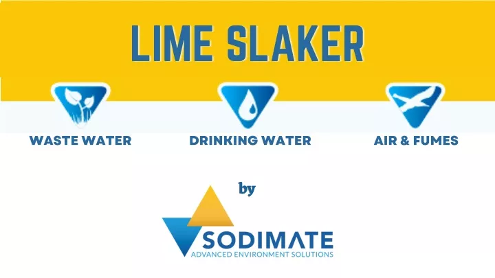
LIME SLAKER LIME SLAKER LIME SLAKER WASTE WATER DRINKING WATER AIR & FUMES by by by
LIME SLAKER LIME SLAKER LIME SLAKER Lime Slaker equipment is used to convert quick lime into hydrated lime. The lime slaking process and its system integration are suitable for the specific needs of every project. CaO + H2O Ca(OH)2+ Heat
LIME SLAKER LIME SLAKER LIME SLAKER
1 Dust free operation 2 Turnkey installation LIME SLAKER LIME SLAKER LIME SLAKER Modular tanks 3 Many options available according to your needs 4 5 Tailored concentration for each process Automatic slaking process for continuous slaking 6
Level sensor 1 Weighting cells 2 Grit removal system 3 LIME SLAKER LIME SLAKER LIME SLAKER 4 Temperature sensors 5 Stainless Steel 304 or 316 6 Pumping skid for lime slurry Manual Flowmeters or Electronic Flowmeters 7 Integrated hydraulic skid along the dilution tank 8
Quicklime and water are dosed in the mixing tank, to achieve a concentration of 250 g/L. The solution is transferred in a dilution tank through an overflow. Water is added to achieve the desired final concentration (usual values are set between 5% and 10%). Steam from the reaction is vacuumed through a vertical or horizontal scrubber.
A cleaning cycle starts by spraying water inside of the scrubber through 2 nozzles. Grids present in the bottom of the preparation tank are periodically removed with wastewater through a valve. A temperature probe and a level sensor ensure a constant concentration in the slaking tank.
DIMENSIONS OF THE PREPARATION TANK DIMENSIONS OF THE PREPARATION TANK OVERALL SIZE ⌀ X ⌀(mm) H (mm) Volume Usable (L) H(mm) 1000 1200 2000 1200 X 2300 2200 2000 1500 1500 X 2900