Download
1 / 1
10 likes | 160 Views
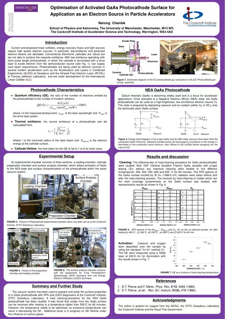
Anode Plate. Stem. Laser. XHV. Electrons. Ceramic. Photocathode. Cathode ball. a. a. a. b. b. b. c. c. c. d. d. d. e. e. e. f. f. f. e -. BINDING ENERGY (eV). BINDING ENERGY (eV). BINDING ENERGY (eV). E affinity. e -. E affinity. h . E g. E g. h . E fermi.

E N D
Anode Plate Stem Laser XHV Electrons Ceramic Photocathode Cathode ball a a a b b b c c c d d d e e e f f f e- BINDING ENERGY (eV) BINDING ENERGY (eV) BINDING ENERGY (eV) Eaffinity e- Eaffinity h Eg Eg h Efermi Efermi GaAs Vacuum GaAs Cs-O Vacuum Surface Analysis Chamber Loading Chamber Preparation Chamber Optimisation of Activated GaAs Photocathode Surface for Application as an Electron Source in Particle Accelerators Narong Chanlek School of Physics and Astronomy, The University of Manchester, Manchester, M13 9PL The Cockcroft Institute of Accelerator Science and Technology, Warrington, WA4 4AD Introduction Current and proposed linear colliders, energy recovery linacs and light sources require high quality electron sources. In particular, low-emittance and polarised electron beams are desirable. Conventional thermionic cathodes are robust but are not able to achieve the requisite emittance. With low emittance operating with short pulse length photocathode, in which the cathode is illuminated with a drive laser to excite electron from the semiconductor source (see Fig. 1), can supply such beam requirements. Photocathodes are being used as electron sources in several modern accelerators such as the Accelerators and Lasers in Combined Experiments (ALICE) at Daresbury and the Infrared Free Electron Laser (IR-FEL) at Thomas Jefferson Laboratory, and are under development for the International Linear Collider (ILC). Figure 1. Schematic diagram of the DC photocathode gun and picture of ALICE Photocathode gun during assembly. NEA GaAs Photocathode Galium Asenide (GaAs) is becoming widely used and is a focus for accelerator applications. Once activated to a Negative Electron Affinity (NEA) state, the GaAs photocathode can be used as a high-brightness, low emmitance electron source [1]. This state is prepared by depositing caesium and an oxidant (either O2 or NF3) onto the atomically-clean GaAs surface. • Photocathode Characteristics • Quantum efficiency (QE), the ratio of the number of electrons emitted by the photocathode to the number of incident photons, • where I is the measured photocurrent, laser is the laser wavelength and Plaser is the drive laser power. • Thermal emittance, the source emittance of a photocathode can be calculated from where r is the hard-wall radius of the laser beam and Ethermal is the electron energy at the cathode surface. • Cathodelifetime, the time taken for the QE to fall to 1/e of its initial value. Figure 2. Energy band diagram of (a) p-type GaAs and (b) NEA state (vacuum level lower than the conduction band minimum). Electrons excited across the band gap Eg by photons of the energy h thermalise to the conduction band minimum, then diffuse to the surface before escaping into the vacuum [2]. Experimental Setup An experimental chamber consists of three sections, a loading chamber, cathode preparation chamber and surface analysis chamber, which allows activation of GaAs to the NEA state and surface characterisation of the photocathode within the same vacuum system. Results and discussion Cleaning: The effectiveness of heat-cleaning procedure for GaAsphotocathodes were studied. Bulk VGF (Vertical Gradient Freeze) GaAs samples with p-type doping (Zn) without any chemical cleaning were heated to five different temperatures; 450, 500, 550, 600 and 625 C for 60 minutes. The XPS spectra of the GaAs surface excited by Al K(1486.6 eV) radiation were taken before and after the heat-cleaning process. The removal by heat-cleaning of oxides which are the main coverage contaminants on the GaAs surface was studied, with representative results as shown in Fig. 6. FIGURE 3. Picture of Photocathode experimental chamber which has been set up at the Cockcroft Institute, STFC Daresbury Laboratory. Loading Chamber Cs dispenser Hemispherical analyser for XPS Inert sputter ion source FIGURE 6. XPS spectra of the As2p3/2 , Ga2p3/2 and O1sfor (a) the un-cleaned sample, (b) after heating to 450C, (c) 500C, (d) 550C, (e) 600C and (f) 625C for 60 min. Ion pump Activation: Caesium and oxygen were deposited onto the sample by using the standard “Yo-Yo” method [1] . The QE were measured using a HeNe laser at 632.8 nm for illumination with the results shown in Fig. 7. Hydrogen cracker source Penning Gauge RGA NEG pump FIGURE 5. The surface analysis chamber contains with the equipments for X-ray Photoelectron Spectroscopy (XPS) technique and Low Energy Electron Diffraction (LEED) technique . FIGURE 4. Picture of the preparation chamber and loading chamber FIGURE 7. QE as a function of heat-cleaning temperature. • References • 1. D.T. Pierce and F. Meier, Phys. Rev. B 13, 5484 (1980). • D.T. Pierce, et.all., Rev. Sci. Instrum. 51(4), 478 (1980). Summary and Further Study The vacuum system has been used to prepare and study the surface properties of a GaAs photocathode with XPS and LEED diagnostics at the Cockcroft Institute, STFC Daresbury Laboratory. A heat cleaning-procedure for the NEA GaAs photocathode has been studied. It was found that oxides from the GaAs surface can be removed after heating to a temperature higher than 550C for 60 minutes. However, the temperature needs to be optimised, as excessive temperatures can result in decreasing the QE . Additional study is in progress on QE lifetime under the influence of various gases. Acknowledgments The author is grateful for support from the ASTeC, the STFC Daresbury Laboratory, the Cockcroft Institute and the Royal Thai Government .