Download
1 / 19
370 likes | 729 Views
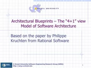
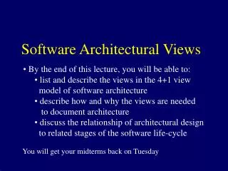
4+1 View Model of Software Architecture. “Software architecture ” Lecture 2. Outline. Problem Solution 4+1 view model Logical view Process view Development view Physical view Scenarios The Iterative process Remarks. Problem.

E N D
4+1 View Model of Software Architecture “Software architecture” Lecture 2
Outline • Problem • Solution • 4+1 view model • Logical view • Process view • Development view • Physical view • Scenarios • The Iterative process • Remarks
Problem • Arch. documents over-emphasize an aspect of development and do not address the concerns of all stakeholders • Various stakeholders of software system: end-user, developers, system engineers, project managers • Software engineers struggled to represent more on one blueprint, and so arch. documents contain complex diagrams
Solution • Using several concurrent views or perspectives, with different notations(Data/details/information) each one addressing one specific set for concerns • “4+1” view model presented to address large and challenging architectures
4+1 View Model of Architecture End user Logical view Development view Programmers & software managers Scenarios Process View Physical View System Engineer Integrator
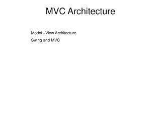
Logical View Viewer:End-user considers:Functional requirements- What the system should provide in terms of services to its users. The logical view is concerned with the functionality that the system provides to end-users. UML Diagrams used to represent the logical view include Class diagram, Communication diagram, Sequence diagram.
Process View (The process decomposition) viewer:Integrators considers: Non - functional requirements (concurrency, performance, scalability)
Process View con’t • The process view deals with the active aspects of the system, explains the system processes and how they communicate, and focuses on the runtime behavior of the system. • The process view addresses concurrency, distribution, integrators, performance, and scalability, etc. • UML Diagrams to represent process view include the Activity diagram
Development View (Subsystem decomposition) Viewer: Programmers and Software Managers considers: software module organization (Hierarchy of Components, software management, reuse, constraints of tools)
Development View Con’t • The development view demonstrate a system from a programmer's perspective and is concerned with software management. • This view is also known as the implementation view. • It uses the UML Component diagram to describe system components. UML Diagrams used to represent the development view include the Package diagram.
Physical View (Mapping the software to the Hardware) Viewer:System Engineers Considers:Non-functional req. regarding to underlying hardware (Topology, Communication) May Tightly connected to the process view
Physical View Con’t • The physical view depicts the system from a system engineer's point-of-view. It is concerned with the topology of software components, as well as the physical connections between these components. • This view is also known as the deployment view. • UML Diagrams used to represent physical view include the Deployment diagram.
4+1 View Model of Architecture End user Logical view Development view Programmers & software managers Scenarios Process View Physical View System Engineer Integrator
Scenarios (Putting it all together) Viewer:All users of other views and Evaluators. Considers:System consistency, validity • Help demonstrate and validate the document • Help Architect during the architecture design
Scenarios Con’t • The description of an architecture is demonstrated using a small set of use cases, or scenarios which become a fifth view. • The scenarios describe sequences of interactions between processes. • They are used to identify architectural elements • And to illustrate and validate the architecture design. • They also serve as a starting point for tests of an architecture model.
Correspondence between views • Views are interconnected. • Start with Logical view (Req. Doc) and Move to Development or Process view and then finally go to Physical view. • Two strategy to analyse level of harmony: • Inside-out: starting from Logical structure • Outside-in: starting from physical structure
4+1 View Model of Architecture End user Logical view Development view Programmers & software managers Scenarios Process View Physical View System Engineer Integrator
The Iterative process • Not all software arch. Need all views. • A scenario-driven approach to develop the system • Documentation: • Software architecture document • Software design guidelines
Remarks • Methodology successfully used in the industry • Air Traffic Control • Telecom • Comprehensive: All other views are reducible to one of the 4 views