Download
1 / 22
220 likes | 324 Views
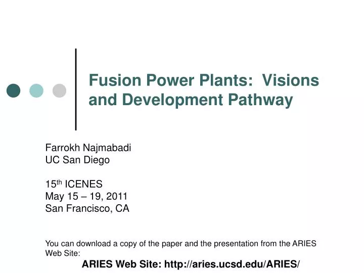
Fusion Power Plants: Visions and Development Pathway. Farrokh Najmabadi UC San Diego 15 th ICENES May 15 – 19, 2011 San Francisco, CA You can download a copy of the paper and the presentation from the ARIES Web Site: ARIES Web Site: http://aries.ucsd.edu/ARIES/.

E N D
Fusion Power Plants: Visions and Development Pathway Farrokh Najmabadi UC San Diego 15th ICENES May 15 – 19, 2011 San Francisco, CA You can download a copy of the paper and the presentation from the ARIES Web Site: ARIES Web Site: http://aries.ucsd.edu/ARIES/
The ARIES Team Has Examined Many Fusion Concepts As Power Plants Criteria for power plant attractiveness were developed in consultation with Electric Utilities and Industry Focus of the talk is on Tokamak studies: ARIES-I first-stability tokamak (1990) ARIES-III D-3He-fueled tokamak (1991) ARIES-II and -IV second-stability tokamaks (1992) Pulsar pulsed-plasma tokamak (1993) Starlite study (1995) (goals & technical requirements for power plants & Demo) ARIES-RS reversed-shear tokamak (1996) ARIES-AT advanced technology and advanced tokamak (2000)
Nature of Power Plant Studies has evolved in time. • Concept Exploration (< 1990) • Limited physics/engineering trade-offs due to lack of physic understanding. • The only credible vision was a large, expensive pulsed tokamak with many engineering challenges (e.g., thermal energy storage). • Concept Definition ( ~ 1990-2005) • Finding credible embodiments (Credible in a “global” sense). • Better physics understanding allowed optimization of steady-state plasma operation and physics/engineering trade-offs. • Concept Feasibility and Optimization (> 2010) • Detailed analysis of subsystems to resolve feasibility issues. • Trade-offs among extrapolation and attractiveness.
Pulsar* ARIES-I’ Current-drive system PF System Very expensive but efficient Non-inductive drive Expensive & inefficient Recirculating Power Low High Optimum Plasma Regime High Bootstrap, High A, Low I High Bootstrap, High A, Low I Current profile Control No, 30%-40% bootstrap fraction bN~ 3, b ~ 2.1% Yes, 65-%-75% bootstrap fraction, bN~ 3.3, b ~ 1.9% Toroidal-Field Strength Lower because of interaction with PF (B ~ 14 T on coil) Higher (B ~ 16 T on coil) Power Density Low Medium Size and Cost High (~ 9 m major radius) Medium (~ 8 m major radius) For the same physics and technology basis, steady-state devices outperform pulsed tokamaks * Many engineering challenges such as thermal energy storage, lower performance of fusion core due to thermal cycling, etc.
Improving Economic Competitiveness Mass power density= net electric output / mass of fusion core QE = net electric output / recirculating electric power Reducing life-cycle cost: • 80s goals: • Low recirculating power; • High power density; • Later Additions • High thermal conversion efficiency; • Less-expensive systems.
Increase Power Density (1/Vp) What we pay for,VFPC High-Field Magnets • Little Gain Big Win • ARIES-I with 19 T at the coil (cryogenic). • Advanced SSTR-2 with 21 T at the coil (HTS). D r r > D r ~ D r < D High bootstrap, High b • 2nd Stability: ARIES-II/IV • Reverse-shear: ARIES-RS, ARIES-AT, A-SSRT2 Decrease Recirculating Power Fraction Directions for Improvement • Improvement “saturates” at ~5 MW/m2 peak wall loading (for a 1GWe plant). • A steady-state, first stability device with Nb3Sn technology has a power density about 1/3 of this goal. • Improvement “saturates” at plasma Q ~ 40. • A steady-state, first stability device with Nb3Sn Tech. has a recirculating fraction about 1/3 of this goal.
COE insensitive of power density COE insensitive of current drive Evolution of ARIES Tokamak Designs
Estimated Cost of Electricity (1992 c/kWh) Major radius (m) High Thermal Efficiency High b is used to lower magnetic field Approaching COE insensitive of power density A range of attractive tokamak power plants is available.
Fusion Technologies Have a Dramatic Impact of Attractiveness of Fusion
ARIES-I Introduced SiC Composites as A High-Performance Structural Material for Fusion SiC composites are attractive structural material for fusion • Excellent safety & environmental characteristics (very low activation and very low afterheat). • High performance due to high strength at high temperatures (>1000oC). • Large world-wide program in SiC: • New SiC composite fibers with proper stoichiometry and small O content. • New manufacturing techniques based on polymer infiltration or CVI result in much improved performance and cheaper components. • Recent results show composite thermal conductivity (under irradiation) close to 15 W/mK which was used for ARIES-I.
Many issues with solid breeders; Rankine cycle efficiency saturated at high temperature Max. coolant temperature limited by maximum structure temperature Improved Blanket Technology High efficiency with Brayton cycle at high temperature Continuity of ARIES research has led to the progressive refinement of research • ARIES-I: • SiC composite with solid breeders • Advanced Rankine cycle • ARIES-RS: • Li-cooled vanadium • Insulating coating • ARIES-ST: • Dual-cooled ferritic steel with SiC inserts • Advanced Brayton Cycle at 650 oC • ARIES-AT: • LiPb-cooled SiC composite • Advanced Brayton cycle with h = 59%
ARIES-AT features a high-performance blanket Outboard blanket & first wall • Simple, low pressure design with SiC structure and LiPb coolant and breeder. • Innovative design leads to high LiPb outlet temperature (~1,100oC) while keeping SiC structure temperature below 1,000oC leading to a high thermal efficiency of ~ 60%. • Simple manufacturing technique. • Very low afterheat. • Class C waste by a wide margin.
PbLi Inlet Temp. = 764 °C Max. SiC/SiC Temp. = 996°C Max. SiC/PbLi Interf. Temp. = 994 °C Bottom Top PbLi Outlet Temp. = 1100 °C Design leads to a LiPb Outlet Temperature of 1,100oC While Keeping SiC Temperature Below 1,000oC • Two-pass PbLi flow, first pass to cool SiCf/SiC box second pass to superheat PbLi
Modular sector maintenance enables high availability • Full sectors removed horizontally on rails • Transport through maintenance corridors to hot cells • Estimated maintenance time < 4 weeks ARIES-AT elevation view
After 100 years, only 10,000 Curies of radioactivity remain in the 585 tonne ARIES-RS fusion core. Radioactivity levels in fusion power plantsare very low and decay rapidly after shutdown • SiC composites lead to a very low activation and afterheat. • All components of ARIES-AT qualify for Class-C disposal under NRC and Fetter Limits. 90% of components qualify for Class-A waste. Ferritic Steel Vanadium Level in Coal Ash
Blanket 1 (replaceable) Blanket 2 (lifetime) Shield (lifetime) • Only “blanket-1” and divertors are replaced every 5 years Fusion Core Is Segmented to Minimize the Rad-Waste
Waste volume is not large • 1270 m3 of Waste is generated after 40 full-power year (FPY) of operation. • Coolant is reused in other power plants • 29 m3 every 4 years (component replacement), 993 m3 at end of service • Equivalent to ~ 30 m3 of waste per FPY • Effective annual waste can be reduced by increasing plant service life. • 90% of waste qualifies for Class A disposal
Nature of Power Plant Studies has evolved in time. • Concept Exploration (< 1990) • Limited physics/engineering trade-offs due to lack of physic understanding. • The only credible vision was a large, expensive pulsed tokamak with many engineering challenges (e.g., thermal energy storage). • Concept Definition ( ~ 1990-2005) • Finding credible embodiments (Credible in a “global” sense). • Better physics understanding allowed optimization of steady-state plasma operation and physics/engineering trade-offs. • Concept Feasibility and Optimization (> 2010) • Detailed analysis of subsystems to resolve feasibility issues. • Trade-offs among extrapolation and attractiveness.
ITER has changed the magnetic fusion landscape • ITER has heightened understanding of many subsystem issues: • New sets of physics information/correlations has been developed to define design requirements for many subsystems (e.g., in-vessel components, transients). • Realities of designing practical systems to be built. • Increased interest in fusion nuclear engineering and material • Realization that new material and technologies have to be developed now.
New Paradigms for Power Plant Studies in the ITER area • Detailed design of subsystems in context of a power plant environment and constraints • Can only be done one system at a time. • Parametric surveys to understand physics/engineering trade-offs. • Sophisticated computational tools are now widely available. • Interaction with material and R&D community to indentify material properties and R&D needs. • Current ARIES project is focusing on detailed design of in-vessel components. • System Tools to analyze trade-offs among R&D risks and benefits. • A new System approach based on the survey of parameter space as opposed to optimizing to a design point.