Download
1 / 35
350 likes | 355 Views
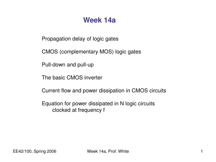
Week 14a. Propagation delay of logic gates CMOS (complementary MOS) logic gates Pull-down and pull-up The basic CMOS inverter Current flow and power dissipation in CMOS circuits Equation for power dissipated in N logic circuits clocked at frequency f. EXAMPLE.

E N D
Week 14a Propagation delay of logic gates CMOS (complementary MOS) logic gates Pull-down and pull-up The basic CMOS inverter Current flow and power dissipation in CMOS circuits Equation for power dissipated in N logic circuits clocked at frequency f Week 14a, Prof. White
EXAMPLE WHAT IS THE ORIGIN OF GATE DELAY? Logic gates are electronic circuits that process electrical signals Most common signal for logic variable: voltage Specific voltage ranges correspond to “0” or “1” Thus delay in voltage rise or fall (because of delay in charging internal capacitances) will translate to a delay in signal timing Note that the specific voltage range for 0 or 1 depends on “logic family,” and in general decreases with succeeding logic generations Week 14a, Prof. White
Inverter inside a large system INVERTER VOLTAGE WAVEFORMS (TIME FUNCTIONS) Inverter input is vIN(t), output is vOUT(t) Vin(t) t Week 14a, Prof. White
Vin(t) 1.5 t Approximation tD tD tD GATE DELAY (PROPAGATION DELAY) Define as the delay required for the output voltage to reach 50% of its final value. In this example we will use 3V logic, so halfway point is 1.5V. Inverters are designed so that the gate delay is symmetrical (rise and fall) Vout(t) 1.5 t Week 14a, Prof. White
How fast is this? Speed of light: c = 3 108 m/s Distance traveled in 57 ps is: c X tD = (3x10⁸m/s)(57x10-12s) = 17 x 10-4 m = 1.7cm EFFECT OF PROPAGATION DELAY ON PROCESSOR SPEED Computer architects would like each system clock cycle to have between 20 and 50 gate delays … use 35 for calculations Implication: if clock frequency = 500 MHz clock period = (5108 s1)1 Period = 2 10 9s = 2 ns (nanoseconds) Gate delay must be tD = (1/35) Period = (2 ns)/35 = 57 ps (picoseconds) Week 14a, Prof. White
WHAT DETERMINES GATE DELAY? The delay is mostly simply the charging of the capacitors at internal nodes. Logic gates consist of just “CMOS” transistor circuits (CMOS = complementary metal-oxide-semiconductor = NMOS and PMOS FETs together). Let’s recall the FET Week 14a, Prof. White
Modern Field Effect Transistor (FET) • An electric field is applied normal to the surface of the semiconductor (by applying a voltage to an overlying “gate” electrode), to modulate the conductance of the semiconductor • Modulate drift current flowing between 2 contacts (“source” and “drain”) by varying the voltage on the “gate” electrode N-channel metal-oxide- semiconductor field-effect transistor (NMOSFET) Week 14a, Prof. White
Pull-Down and Pull-Up Devices • In CMOS logic gates, NMOSFETs are used to connect the output to GND, whereas PMOSFETs are used to connect the output to VDD. • An NMOSFET functions as a pull-down device when it is turned on (gate voltage = VDD) • A PMOSFET functions as a pull-up device when it is turned on (gate voltage = GND) VDD A1 A2 AN Pull-up network input signals PMOSFETs only … F(A1, A2, …, AN) A1 A2 AN Pull-down network NMOSFETs only … Week 14a, Prof. White
+ + + + RN - - - - G Output + Input S RP G Output + Input - S Controlled Switch Model Type N controlled switch” means switch is closed if input is high. (VG > VS) - Type P controlled switch” means switch is closed if input is low. (VG < VS) Now lets combine these switches to make an inverter. Week 14a, Prof. White
i i i The CMOS Inverter: Current Flow during Switching N: sat P: sat V OUT N: off C V P: lin DD V DD S G N: sat P: lin D V V IN OUT B D E A D G N: lin S P: sat N: lin P: off 0 V IN V 0 DD Week 14a, Prof. White
VDD-VT VT Ipeak 0 tsc Energy consumed per switching period: CMOS Inverter Power Dissipation due to Direct-Path Current VDD V DD vIN: S G 0 D i vIN vOUT D G i: S time Note: once the CMOS circuit reaches a steady state there’s no more current flow and hence no more power dissipation! Week 14a, Prof. White
VDD = 2V - SP is closed if VIN < VDD SP + RP VOUT VIN + + RN Input Output SN is closed if VIN > VSS + SN - - - VSS = 0V Controlled Switch Model of Inverter So if VIN is 2V then SN is closed and SP is open. Hence VOUT is zero. But if VIN is 0V then SP is closed and SN is open. Hence VOUT is 2V. Week 14a, Prof. White
VDD = 2V VIN =2V + VOUT RN - VSS = 0V VDD = 2V - RP VIN =0V + VOUT - - VSS = 0V Controlled Switch Model of Inverter IF VIN is 2V then SN is closed and SP is open. Hence VOUT is zero (but driven through resistance RN). But if VIN is 0V then SP is closed and SN is open. Hence VOUT is 2V (but driven through resistance RP). Week 14a, Prof. White
Controlled Switch Model of Inverter – load capacitor charging and discharging takes time VDD = 2V VIN =2V + VOUT RN - VSS = 0V VOUT VDD = 2V - VIN jumps from 2V to 0V RP VIN =0V + VIN jumps from 0V to 2V VOUT t - - VSS = 0V IF there is a capacitance at the output node (there always is) then VOUT responds to a change in VIN with our usual exponential form. Week 14a, Prof. White
Pull-up network is modeled as an open switch Pull-down network is modeled as a resistor Calculating the Propagation Delay Model the MOSFET in the ON state as a resistive switch: Case 1: Vout changing from High to Low (input signal changed from Low to High) • NMOSFET(s) connect Vout to GND tpHL= 0.69RnCL VDD vIN = VDD + vOUT CL Rn Week 14a, Prof. White
Pull-up network is modeled as a resistor Pull-down network is modeled as an open switch Calculating the Propagation Delay (cont’d) Case 2: Vout changing from Low to High (input signal changed from High to Low) • PMOSFET(s) connect Vout to VDD tpLH = 0.69RpCL VDD Rp vIN = 0 V + vOUT CL Week 14a, Prof. White
“intrinsic capacitance” “extrinsic capacitance” Output Capacitance of a Logic Gate • The output capacitance of a logic gate is comprised of several components: • pn-junction and gate-drain capacitance • both NMOS and PMOS transistors • capacitance of connecting wires • input capacitances of the fan-out gates Week 14a, Prof. White
1 2 fan-out =N • • • driving gate N Reminder: Fan-Out • Typically, the output of a logic gate is connected to the input(s) of one or more logic gates • The fan-out is the number of gates that are connected to the output of the driving gate: • Fanout leads to increased capacitive load on the • driving gate, and therefore more propagation delay • The input capacitances of the driven gates sum, and must be • charged through the equivalent resistance of the driver Week 14a, Prof. White
Minimizing Propagation Delay • A fast gate is built by • Keeping the output capacitance CL small • Minimize the area of drain pn junctions. • Lay out devices to minimize interconnect capacitance. • Avoid large fan-out. • Decreasing the equivalent resistance of the transistors • Decrease L (gate length source to drain) • Increase W (other dimension of gate) … but this increases pn junction area and hence CL • Increasing VDD • trade-off with power consumption & reliability Week 14a, Prof. White
L = channel length W • W = channel width n n L oxide insulator MOSFET • NMOS:N-channel Metal • Oxide Semiconductor GATE “Metal” (heavily doped poly-Si) DRAIN p-type silicon SOURCE • A GATE electrode is placed above (electrically insulated from) the silicon surface, and is used to control the resistance between the SOURCE and DRAIN regions Week 14a, Prof. White
VDD S G D VOUT VIN D G S Transistor Sizing for Performance • Widening the transistors reduces resistance – current paths in parallel -- but increases gate capacitance • In order to have the on-state resistance of the PMOS transistor match that of the NMOS transistor (e.g. to achieve a symmetric voltage transfer curve), its W/L ratio must be larger by a factor of~3 (because holes move about 3 times slower than electrons in a given electric field). Week 14a, Prof. White
Other CMOS logic examples Week 14a, Prof. White
CMOS NAND Gate VDD A B F A B Week 14a, Prof. White
CMOS NOR Gate VDD A B F A B Week 14a, Prof. White
Static Random-Access Memory (SRAM) with CMOS Circuit in each cell Week 14a, Prof. White
Power consumption in CMOS circuits Week 14a, Prof. White
CASE 1-Charging R t=0 i VDD C RD Power into R Power into C Power out of "battery" ¥ 1 2 = E iV dt CV ò C C DD This must be difference of E and EC, i.e. 2 0 1 = 2 CV DD 2 ENERGY AND POWER IN CHARGING/DISCHARGING CAPACITORS – A REVIEW Capacitor initially uncharged (Q=CVDD at end) Switch moves @ t=0 Energy into R (heat) Energy into C Energy out of "battery" Week 14a, Prof. White
R t=0 VDD C RD 1 2 CV DD 2 1 = 2 CV DD 2 ENERGY AND POWER IN CHARGING Capacitor initially uncharged (Q=CVDD at end) Switch moves @ t=0 Energy into R (heat) Energy into C Energy out of "battery" In charging a capacitor from a fixed voltage source VDD half the energy from the source is delivered to the capacitor, and half is lost to the charging resistance, independent of the value of R. Week 14a, Prof. White
Power into RD Power out of C Power out of battery ¥ 1 2 = E iV dt CV ò This must be energy initially in C, i.e. C C DD 2 0 Power in/out of R =0 1 = 2 CV DD 2 ENERGY AND POWER IN CHARGING/DISCHARGING CAPACITORS CASE 2-discharging R t=0 Capacitor initially charged (Q=CVDD) and discharges. VDD C RD i Switch moves @ t=0 =0 Energy into RD (heat) Energy out of C Energy out of battery =0 Week 14a, Prof. White
1 2 CV DD 2 1 = 2 CV DD 2 ENERGY IN DISCHARGING CAPACITORS R t=0 Capacitor initially charged (Q=CVDD) and discharges. VDD C RD Switch moves @ t=0 Energy out of C Energy into RD (heat) When a capacitor is discharged into a resistor the energy originally stored in the capacitor (1/2 CVDD2) is dissipated as heat in the resistor Week 14a, Prof. White
CMOS Power Consumption • The total power consumed by a CMOS circuit is comprised of several components: • Dynamic power consumption due to charging and discharging capacitances*: f01 = frequency of 01 transitions (“switching activity”) f = clock rate (maximum possible event rate) Effective capacitanceCEFF = average capacitance charged every clock cycle * This is typically by far the dominant component! Other components of power dissipation are direct current flow during part of the CMOS switching cycle and leakage in the transistor junctions. Week 14a, Prof. White
POWER DISSIPATION in DIGITAL CIRCUITS Each node transition (i.e. charging or discharging) results in a loss of (1/2)(C)(VDD2)How many transitions occur per second? Well if the node is pulsed up then down at a frequency f (like a clock frequency) then we have 2f dissipation events. A system of N nodes being pulsed at a frequency f to a signal voltage VDD will dissipate energy equal to (N) (2f )(½CVDD2)each second Therefore the average power dissipation is (N) (f )(CVDD2) Week 14a, Prof. White
LOGIC POWER DISSIPATION EXAMPLE Power = (Number of gates) x (Energy per cycle) x (frequency) P = (N) (CVDD2)(f ) • N = 107; VDD = 2 V; node capacitance = 10 fF; f = 109 s-1 (1GHz) • P = 400 W! -- a toaster! • Pretty high but realistic • What to do?(N increases, f increases, hmm) • Lower VDD • Turn off the clock to the inactive nodes Clever architecture and design! Let’s define a as the fraction of nodes that are clocked (active). Then we have a new formula for power. Week 14a, Prof. White
LOGIC POWER DISSIPATION with power mitigation Power = (Energy per transition) x (Number of gates) x (frequency) x fraction of gates that are active (a). P = a N CVDD2 f In the last 5 years VDD has been lowered from 5V to about 1.5V. It cannot go very much lower. But with clever design, we can make a as low as 1 or 10%. That is we do not clock those parts of the chip where there is no computation being made at the moment. Thus the 400W example becomes 4 to 40W, a manageable range (4W with heat sink, 40W with heat sink plus fan on the chip). Week 14a, Prof. White
Low-Power Design Techniques • Reduce VDD • quadratic effect on Pdyn Example: Reducing VDD from 2.5 V to 1.25 V reduces power dissipation by factor of 4 • Lower bound is set by VT: VDD should be >2VT • Reduce load capacitance • Use minimum-sized transistors whenever possible • Reduce the switching activity • involves design considerations at the architecture level (beyond the scope of this class!) Week 14a, Prof. White