Download
1 / 35
360 likes | 632 Views
Prof. Sirer CS 316 Cornell University. Flip-flops, Latches and State. Early Transistors. The first transistor, on a workbench at AT&T Bell Laboratories in 1947. Logic Gates. One can buy gates separately ex. 74xxx series of integrated circuits

E N D
Prof. Sirer CS 316 Cornell University Flip-flops, Latches and State
Early Transistors • The first transistor, on a workbench at AT&T Bell Laboratories in 1947
Logic Gates • One can buy gates separately • ex. 74xxx series of integrated circuits • cost ~$1 per chip, mostly for packaging and testing • Cumbersome, but possible to build devices using gates put together manually
Integrated Circuits • Or one can manufacture a complete design using a custom mask • An Intel Pentium has approximately 125 million transistors
Special-Purpose Transistors • A photo-sensitive transistor can be used to detect the presence of light • Photo-sensitive material triggers the gate
Recap • We have enough tools in our arsenal to start build interesting devices • Let’s build a Scantron device • Elections are coming up! • Background: • A vote is recorded on a piece of paper, • by punching out a whole, • there are at most 7 choices • we will not worry about “hanging chads” or “invalids” • For now, let’s just display the numerical identifier to the ballot supervisor • we won’t do counting yet, just decoding • we can use four photo-sensitive transistors to find out which hole is punched out
Ballot Reading • All we want to do is go from a paper with a hole in it to a number the ballot supervisor can record Ballots The super-duper 316 vote decoding machine
Demultiplexors/Encoders a 1 • N sensors in a row • We want to distinguish which sensor of the N sensors has fired • Want to represent the firing sensor number in compact form • N might be large, I want to sell this device to Italy • Only one wire is on at any time • Silly to route N wires everywhere, better to encode in log N wires o0 b 2 o1 c 3 o2 d 4 A 3-bit (7-to-3) encoder (4 inputs shown)
Number Representations 37 • Decimal numbers are written in base 10 • 3 x 101 + 7 x 100 = 37 • Just as easily use other bases • Base 2 - “Binary” • Base 8 - “Octal” • Base 16 – “Hexadecimal” • Base conversion via repetitive division • Divide by base,write remainder,move left with quotient • Sanity check with 37 and 10 101 100
Binary Representation • 37 = 32 + 4 + 1 0100101 26 25 24 23 22 21 20 64 32 16 8 4 2 1
Hexadecimal Representation 25 • 37 decimal = (25)16 • Convention • Base 16 is written with a leading 0x • 37 = 0x25 • Need extra digits! • 0, 1, 2, 3, 4, 5, 6, 7,8, 9, A, B, C, D, E, F • Binary to hexadecimal is easy • Divide into groups of 4, translate groupwise into hex digits 161 160
Encoder Truth Table a 1 o0 b 2 o1 o1 c 3 o2 d 4 • o2 = abcd • o1 = abcd + abcd • o0 = abcd + abcd A 3-bit encoder with 4 inputsfor simplicity
Ballot Reading • Ok, we builtfirst half of the machine • Need to display the result Ballots The super-duper 316 vote decoding machine
7-Segment LED Decoder • 4 inputs encoded in binary • 8 outputs, each driving an independent, rectangular LED • Can display numbers • Just a simple logic circuit • Write the truth table
7-Segment LED Decoder • 4 inputs encoded in binary • 8 outputs, each driving an independent, rectangular LED • Can display numbers 1 0 0 0
7-Segment LED Decoder • 4 inputs encoded in binary • 8 outputs, each driving an independent, rectangular LED • Can display numbers 1 0 1 0
7-Segment Decoder Truth Table o1 o0 o2 o3 o4 o6 o5 Exercise: find the error(s) in this truth table
7-Segment Decoder Truth Table o1 o0 o2 o3 o4 o6 o5
Ballot Reading • Done! • Off to the patent office! Ballots The super-duper 316 vote decoding machine
Keyboard • Let’s build a keyboard • Lots of mechanical switches • Need to convert to a compact form (binary) • We’ll use a special mechanical switch that, when pressed, connects two wires simultaneously
Keyboard + • When a key is pressed, a 7-bit key identifier is computed 3-bitencoder (4 to 3) 4-bitencoder (16 to 4) not all 16 wires are shown
Stateful Components • Everything we did until now is combinatorial logic • Output is computed when inputs are present • The system has no internal state • Nothing computed in the present can depend on what happened in the past! • Need a way to record data • Need a way to build stateful circuits • Need a state-holding device
Bistable Devices • In stable state, A = B • How do we change the state? A B A Simple Device 1 0 0 1 A B A B
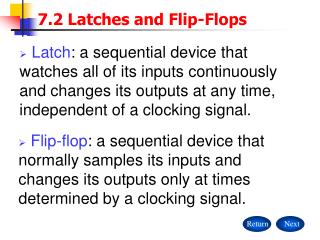
SR Latch Q R • Set-Reset (S-R) Latch • Q: Stored value and its complement • S=1 and R=1 ? S Q
D Latch Q • Data Latch • Easier to use than an SR latch • No possibility of entering an undefined state • When D changes, Q changes • … immediately • Need to control when the output changes R D S Q
Clocks • Clocks help with modifying the contents of state-holding elements • A free running signal • Generated by an oscillating crystal • Clock signal has a fixed cycle time (aka cycle period) • Clock frequency = 1/cycle time risingedge fallingedge 1 0 clock period clock high clock low
Edge-triggering • Can design circuits to change on the rising or falling edge • Trigger on rising edge = positive edge-triggered • Trigger on falling edge = negative edge-triggered • Inputs must be stable just before the triggering edge input clock
First Attempt D S • How does the output behave? Q R Q clk D Q D Q clk Q Q
First Attempt D S • How does the output behave? Q R Q clk clk D Q
First Attempt D S • How does the output behave? • Changes in D that occur when the clock is low are deferred until clock high • Changes when clock is high are registered immediately Q R Q clk D Q D Q clk Q Q
Master-Slave Flip-Flop D Q D Q • Outputs change only on falling edges • Data is captured on rising edges • 1 cycle delay • but works out perfectly – data for the next stage is ready 1 cycle ahead of time X Q Q clk D X Q
Keyboard + • When a key is pressed, a 7-bit key identifier is computed • Let’s store this keycode • The computer may not be ready to read it right away 3-bitencoder (4 to 3) 4-bitencoder (16 to 4) not all 16 wires are shown
Registers D0 D Q D Q • A register is simply a set of master-slave flip-flops in parallel with a shared clock D1 D Q D Q D2 D Q D Q 4-bit reg 4 4 D3 D Q D Q clk
Keyboard with Last Key Display + 4-bit reg 7 seg deco 3-bitencoder (4 to 3) 4-bitencoder (16 to 4) not all 16 wires are shown 7 seg deco 4-bit reg
Summary • We can now build interesting devices with sensors • Using combinatorial logic • We can also store data values • In state-holding elements • Coupled with clocks