Download
1 / 20
200 likes | 204 Views
This paper provides an overview of the EU DEMO design and R&D activities, including challenges, concept design approach, and highlights of achievements. It also discusses the roadmap towards a demonstration fusion power plant and the strategic missions to tackle critical fusion challenges.

E N D
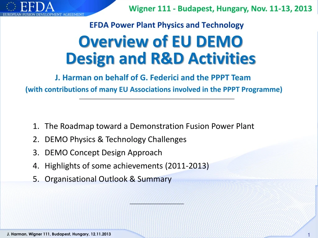
Wigner 111 - Budapest, Hungary, Nov. 11-13, 2013 EFDA Power Plant Physics and Technology Overview of EU DEMO Design and R&D Activities J. Harman on behalf of G. Federici and the PPPT Team (with contributions of many EU Associations involved in the PPPT Programme) • The Roadmap toward a Demonstration Fusion Power Plant • DEMO Physics & Technology Challenges • DEMO Concept Design Approach • Highlights of some achievements (2011-2013) • Organisational Outlook & Summary
New EU Fusion Roadmap • Published in November 2012 • An ambitious yet realistic roadmap to fusion electricity by 2050 • 8 Strategic Missions to tackle the critical challenges for Fusion: • Plasma Operation • Heat Exhaust • Neutron resistant Materials • Tritium-self sufficiency • Safety • Integrated DEMO Design • Competitive Cost of Electricity • Stellarator • Central role of ITER • Industrial Partnerships • Can be downloaded at: http://www.efda.org/
DEMO Programme Timeline The target to generate a few hundred MWe before 2050 is expected to drive much of the design and R&D. 2014 2020 2030 2037 2013 2014 2015 2016 2017 2018 2019 2020 2021 2022 2023 2024 2025 2026 2027 2028 2029 2030 2031 2032 2033 2034 2035 2036 2037 2038 2039 2040 2041 2042 2043 2044 2020 2041 2015 2025 2029 2031 2037 CDR PAR SRR PDR FDR MRR TRR PCA CDA EDA Construction Commissioning/ Operation
Divertor Power Exhaust in DEMO • A reliable Divertor solution is one of the main challenges for DEMO • A risk exists that the baseline ITER design cannot be extrapolated to DEMO • RDEMO/RITER ~ 1.4 but PDEMO/PITER ~ 4 • Scrape-off layer thickness (lq) does not scale with major radius • lq~ 1mm at outer midplane 2cm at the divertor • Peak power flux density (without radiation) • qmax,DEMO1 = 200MW/m2 !! • Therefore, high core radiation levels are needed • At Prad,tot/Ploss=90%, qmax,DEMO1 < 20MW/m2 • But….. • Achieving sufficient radiation at reasonable dilution • Thermal stability • Establish operational experience at high core radiation levels compatible with divertor protection and fusion performance
Tritium Breeding Blankets • Tritium Breeding Blankets - the most important & novel parts of DEMO • Large knowledge gaps will exist even with a successful ITER TBM programme • Feasibility concerns and Performance uncertainties Selection now is premature Nobody’s Perfect !!!
Materials for DEMO Components • Materials R&D affect many DEMO systems and components • EUROFER (8-9%Cr RAFM) – Baseline structural steel from DEMO In-vessel components • Use of EUROFER poses some risks for the DEMO mission: • Low temperature radiation embrittlement • Unknown effect of He embrittlement • Decline in strength above 550°C • Creep-rupture limits operation to <550°C for >12x103hrs • Lack of Design-code development • Incompatibility with Water-cooled blanket/PWR Balance of Plant • Needs a risk mitigation programme on blanket advanced steels. • EUROFER development to lower temperatures • Evidence of some EUROFER steels with superior low temp performance + new JA F82H mod3 data (Shiba, Tanigawa et al) • High temperature FM steels from the non-Fusion programme • Oxide Dispersion Strengthened (ODS) RAFM or Ferritic Steels (Fusion programme) • Note: each ‘back-up’ already on its 10-15 years of development
DEMO Top Level RequirementsAccording to several studies undertaken in Europe • Net electricity production • Several 100 MWs (500 MW) • Low recirculating power maximise overall H&CD efficiency hCDgCD • Tritium self sufficiency – DEMO makes its own fuel • Restrictions on port space for sensors and H&CD. Local TBR ~ 1.1-1.2 • PFC armor must be much thinner to achieve TBR > 1 • Disruptions and ELMs must be reliably eliminated! • A robust solution of all physics and technical issues • Divertor exhaust loads, PFCs • Materials & Technology • Current drive systems • Adequate availability/reliability operation over a reasonable time span • Fast Remote Maintenance schemes – to be developed and demonstrated • Simplifieddesigns (with margins) • Technologies and materials with established industrial manufacturing feasibility (high TRL!) • Safe operation and minimization of radioactive waste
DEMO Concept Design Approach • Initial phase effort to be broad and not focussed on developing a single “design point” • Some flexibility in the approach to the CDA with focused R&D on outstanding issues System Codes 0D/Full System • DEMO1: a large, modest power density, pulsed device with a conventional plasma scenario. • Conservative design • Based on expected performance of ITER • Commence build in 2030’s • DEMO2: a higher power density, high non-inductive CD fraction, steady-state operat. • Optimistic Design • Based on more advanced assumptions • Deliverable in the longer term Plasma Physics Models >0D Subsystems Engineering Models >0D Subsystems • density profile (density limits, peaking) • temperature profile (critical gradients) • plasma dilution and contamination by impurities • radiation compatible with divertor protection and fusion performance • core/pedestal compatible w. beta limits and MHD instabilities Analysis of working points and exploration of scenario using more sophisticated codes
Provisional Design Assumptions Goal-Setting Approach • Use of realistic assumptions for physics and technology: e.g. limiting divertor heat load. • Optimize the device for a purely inductive scenario with a minimum pulse duration (2 hrs) For steady state, minimize size whilst limiting rec (CD) power -> realistic fBS &hCDgCD • Single-null, water-cooled divertor • LTSC magnets (Nb3Sn), max field on conductor 12 T • RAFM (EUROFER) as blanket structural material • n-damage calculations [Gilbert/CCFE 2012]: • ~10 dpa/fpy: FW midplane armour; 6-7 dpa/fpy: divertor W; 2-3 dpa/fpy Cu near strike points • Lifetime operation: • 20 dpa “Starter” blanket, gives 1.33 fpy operation • 50 dpa 2nd blanket • 5 dpa divertor • Safety approach to follow the ITER experience • Vertical Blanket RH schemes to be integrated from the outset • Application of mature BoP technology Technology Assumptions (near-term DEMO)
Provisional DEMO Design Parameters DEMO1 DEMO2 Sensitivity studies underway cover • DEMO 1: blanket properties, fuel cycle, superconductors, divertor, and aspect ratio effects • DEMO 2: H-factor, current-drive efficiency, divertor, aspect ratio, and startup flux swing modelling.
Comparison between ITER and DEMO ITER 2013 ITER 1998 DEMO Reference Geometry 2013 Initial geometry based on System Code Studies Cross Sections through vertical axis
Highlights of some Achievements (2011 to 2013) Magnets: • Proposed LTSC cable designs for DEMO TF Coils • Proposed layered, graded winding pack approach • Parallel programme of HTS R&D for fusion applications TF Coil CICC Prototype Remote Maintenance: • Further developed kinematics / mechanisms for vertical blanket maintenance • CAD-based simulations of maintenance procedures • Initial scoping of Active Maintenance Facility CRPP, Switzerland CCFE, UK Novel Divertor Configurations: • On-going investigations of magnetic coil requirements, design integration and engineering constraints for SnowFlakeand Super-X divertors Snowflake (SF) Quasi Snowflake (QSF) CREATE/ ENEA Italy
Highlights of some Achievements (2011 to 2013) H&CD systems: • An assessment was recently conducted to determine the CD efficiency for a DEMO case • NBI: based on ITER technology (1 MeV) + ion source R&D for Cs elimination • ECRH: gyrotrons up to ~230-250 GHz, with step-tunability and broadband window R&D + top-launch injection • Both ECCD and NBCD are able to synthesize the required current profile ECCD efficiency w.r.t. toroidal and poloidal injection angle E. Poli et. al. IPP Garching) H. Zohm et al., EPS Finland 2013. Vacuum Pumps: • Proof-of-principle testing of continuous operation pumps: • Liquid Metal Diffusion Pump • Liquid Metal Ring Pump • Metal Foil Pump Liquid Metal Ring Pump C. Day, KIT 2013.
Heat Transfer & Balance of Plant Options Primary Loop Coolant Options: • Secondary Loop Coolant Options: • Water / Steam Rankine • Supercritical CO2 Rankine • Organic Fluids Rankine • Helium Brayton (Tout too low!) • Etc. • Energy Storage System considered: • To mitigate fatigue effects of pulsed operation • To smooth grid loading / transients Tokamak Energy Flow Schematic Current Assumption is Indirect Balance of Plant System
Organisation for 2014 and beyond… • EFDA shall expire on 31st December 2013 • EFDA will be replaced by a European Fusion Consortium “EuroFusion” made up of all EU Associations with a coordinating association, to provide financial, legal and administrative functions • The first phase of the roadmap (CDA phase) will be implemented by a number of projects to be executed in the period 2014 to 2020. • Roadmap to be implement through 12 projects • Some directly delivering DEMO systems • Others ensuring system-wide integration of certain aspects • Central project unit necessary for overall technical coordination
Summary • The demonstration of electricity production before 2050 in a DEMO Fusion Power Reactor that produces its own fuel is the primary objective of EU fusion program. • The approach was outlined here together with a preliminary description of the design solutions being considered. • ITER is the key facility in this strategy and the DEMO design/R&D is expected to benefit largely from the experience gained with ITER construction. • Nevertheless, there are still outstanding gaps that need to be overcome requiring a pragmatic approach especially to evaluate and improve through dedicated R&D the readiness of the foreseeable technical solutions. • A system engineering approach is needed and industry must be involved early in the DEMO definition and design. • Availability of sufficient resources and an adequate implementing organization are prerequisite to success. • Europe should seek all the opportunities for international collaborations.