Download
1 / 26
270 likes | 334 Views
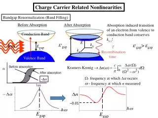
Chapter 6. pn Junction Diodes: I - V Characteristics. Minority-Carrier Charge Storage. When V A >0, excess minority carriers are stored in the quasineutral regions of a pn junction. Chapter 6. pn Junction Diodes: I - V Characteristics. Charge Control Approach.

E N D
Chapter 6 pn Junction Diodes: I-V Characteristics Minority-Carrier Charge Storage • When VA>0, excess minority carriers are stored in the quasineutral regions of a pn junction.
Chapter 6 pn Junction Diodes: I-V Characteristics Charge Control Approach • Consider a forward-biased pn junction. • The total excess hole charge in the n quasineutral region is: • Since the electric field E»0, • Therefore (after all terms multiplied by q), • The minority carrier diffusion equation is (without GL):
Chapter 6 pn Junction Diodes: I-V Characteristics Charge Control Approach • Integrating over the n quasineutral region (after all terms multiplied by Adx), QP QP • Furthermore, in a p+n junction, 0 • So: In steady state
Chapter 6 pn Junction Diodes: I-V Characteristics Charge Control Approach • We can calculate pn junction current in two ways: • From slopes of Δnp(–xp) and Δpn(xn) • From steady-state charges QN and QP stored in each “excess minority charge distribution” • Therefore • Similarly
Chapter 6 pn Junction Diodes: I-V Characteristics Charge Control Approach • Moreover, in a p+n junction: In steady state
Chapter 6 pn Junction Diodes: I-V Characteristics Narrow-Base Diode • Narrow-base diode: a diode where the width of the quasineutral region on the lightly doped side of the junction is on the order of or less than one diffusion length. n-side contact
Chapter 6 pn Junction Diodes: I-V Characteristics Narrow-Base Diode I–V • We have the following boundary conditions: • Then, the solution is of the form: • Applying the boundary conditions, we have:
Chapter 6 pn Junction Diodes: I-V Characteristics Narrow-Base Diode I–V • Solving for A1 and A2, and substituting back: • Note that • The solution can be written more compactly as
Chapter 6 pn Junction Diodes: I-V Characteristics Narrow-Base Diode I–V • With decrease base width, xc’0: • Δpn is a linear function of x due to negligible thermal R–G in region much shorter than one diffusion length • Jp is constant • This approximation can be derived using Taylor series approximation
Narrow-Base Diode I–V Chapter 6 pn Junction Diodes: I-V Characteristics • Because , then • Then, for a p+n junction:
Chapter 6 pn Junction Diodes: I-V Characteristics Narrow-Base Diode I–V • If xc’ << LP, • Resulting • Increase of reverse bias means • Increase of reverse current • Increase of depletion width • Decrease of quasineutral region xc’=xc–xn
Chapter 6 pn Junction Diodes: I-V Characteristics Wide-Base Diode • Rewriting the general solution for carrier excess, • For the case of wide-base diode (xc’>> LP), Back to ideal diode solution
Chapter 6 pn Junction Diodes: I-V Characteristics Wide-Base Diode • Rewriting the general solution for diffusion current, • For the case of wide-base diode (xc’>> LP), Back to ideal diode solution
Chapter 7 pn Junction Diodes: Small-Signal Admittance Small-Signal Diode Biasing • When reversed-biased, a pn junction diode becomes functionally equivalent to a capacitor, whose capacitance decreases as the reverse bias increases. • Biasing additional a.c. signal va can be viewed as a small oscillation of the depletion width about the steady state value. RS : serial resistance C : capacitance G : conductance V0 << VA
Chapter 7 pn Junction Diodes: Small-Signal Admittance Total pn Junction Capacitance Junction / depletion capacitance due to variation of depletion charges Minority carrier lifetime Diffusion capacitance due to variation of stored minority charges in the quasineutral regions • CJ dominates at low forward biases, reverse biases • CD dominates at moderate to high forward biases
Chapter 7 pn Junction Diodes: Small-Signal Admittance Relation Between CJ and VA • For asymmetrical step junction, NB : bulk semiconductor doping, NA or ND as appropriate • Therefore
Chapter 8 pn Junction Diodes: Transient Response Turn-Off Transient • In order to turn the diode off, the excess minority carriers must be removed through net carrier flow out of the quasi-neutral regions and recombination. • Carrier flow is limited by the switching circuit tr : recovery time ts : storage delay time trr : reverse recovery time Diode switching circuit
Chapter 8 pn Junction Diodes: Transient Response Turn-Off Transient • Voltage-time transient The junction remains forward biased for 0 < t < ts vA(t) = 0 at t =ts
Chapter 8 pn Junction Diodes: Transient Response Transient Response of pn Diode • Suppose a pn diode is forward biased, then suddenly turned off at time t = 0. • Because of CD, the voltage across the pn junction depletion region cannot be changed instantaneously • The delay in switching between the ON and OFF states is due to the time required to change the amount of excess minority carriers stored in the quasi-neutral regions.
Chapter 8 pn Junction Diodes: Transient Response i(t) ts t vA(t) t ts Decay of Stored Charge • Consider a p+n diode: Dpn(x) Decrease due to recombination and reverse current flow pn0 x xn • For t > 0: • The diode remains forward biased during0 < t < ts
Chapter 8 pn Junction Diodes: Transient Response i(t) i(t) i(t) ts ts ts t t t Examples i-t transient Decrease tp Increase IF Increase IR
Chapter 8 pn Junction Diodes: Transient Response Storage Delay Time ts • ts is the primary quantity used to characterize the transient response of pn junction diodes QP : excess hole charge • By separation of variables and integration from t = 0+ to t = ts, noting that • And making the approximation of • We may conclude that
Chapter 8 pn Junction Diodes: Transient Response Turn-On Transient • Again, consider a p+n diode: Dpn(x) i(t) A positive current IF is forced to flow through the diode beginning at t = 0 t vA(t) pn0 x xn • For t > 0: t
Chapter 8 pn Junction Diodes: Transient Response Turn-On Transient • Rewriting for turn-on characteristics, • By separation of variables and integration, we have • If we assume that the build-up of stored charge occurs quasistatically so that Steady state • Finally
Chapter 6 pn Junction Diodes: I-V Characteristics Homework 6 • 1. (8.14) • The cross-sectional area of a silicon pn junction is 10–3 cm2. The temperature of the diode is 300 K, and the doping concentrations are ND = 1016 cm–3 and NA = 8×1015 cm–3. Assume minority carrier lifetimes of τn0 = 10–6 s and τp0 = 10–7 s. • Calculate the total number of excess electrons in the p region and the total number of excess holes in the n region for (a) VA = 0.3 V, (b) VA = 0.4V, and (c) VA = 0.5 V. • 2. (7.2) • Problem 8.2, Pierret’s “Semiconductor Device Fundamentals”. • Deadline: 31.03.2011, at 07:30 am.