Download
1 / 50
500 likes | 648 Views
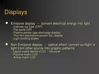
TV Displays System Level Overview. Dec 6 2004 Prinyar Boon. New Displays - Technologies. New raft of new display technologies are now a commercial reality LCD, LCOS, LCD-TFT, DMD, Plasma, LED, OLED, SED, GLV…. Each display technology has a unique set of fundamental characteristics

E N D
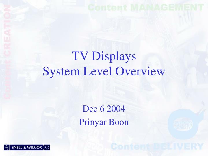
TV DisplaysSystem Level Overview Dec 6 2004 Prinyar Boon
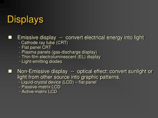
New Displays - Technologies • New raft of new display technologies are now a commercial reality • LCD, LCOS, LCD-TFT, DMD, Plasma, LED, OLED, SED, GLV…. • Each display technology has a unique set of fundamental characteristics • Each Commercial Implementation also has its set of individual characteristics
New Displays - New Opportunities • New technologies present new business opportunities • D-Cinema • E-Cinema • Mobile: Plane, Car, Phone, PDA • E-Billboard • E-Commerce • Digital Photography • Electronic Proof [Print, Film]
New Displays – New Problems • Television - Today • Grade 1 CRT Monitor • Television – Future • LCD, Plasma, DLP, SED, OLED? • Film – Today • 48Hz projector; 4 perf 35mm Ansa-print • Film – Future => D-Cinema • Reference projector
Working Groups • TV Broadcast • SMPTE I23 Display ad hoc group: Dave Bancroft • EBU • TV Domestic • UK: DTG Display working group: David Holliday • Europe: EICTA • Film D-Cinema • SMPTE DC28 Colorimetry ad hoc group: Glenn Kennel • ITU
What does the Display do? • Integral to image rendering process • Electro-optical conversion transfer characteristic [gamma] Linear light output System rendering intent • Implied display filter Partly defines output image contrast [+ Room] Upper bound on image resolution [H,V,T] May directly modify the image • Determines image size and shape [aspect ratio and framing – crop/overscan] • Determines Image Luminance levels • Determines Image Chromaticity
What does the Environment do? • Integral to rendering of the image • Limits image size and shape • Bounds viewing distance • Determines the required display peak luminance [sunlight viewing >5000 nits] • Contrast contributions • Limiting Contrast [room light + reflected light] • Psycho-visual effects • Modifies image Chromaticity • Determinate of system ‘rendering intent’
TV: Origins Studio • Studio Reference Monitor defined as CRT…Alas: • Display Gamma ‘assumed’ [2.1 – 2.8?] • Channel coding Gamma not defined • Temporal characteristics - not defined • CRT is also part of the “display filter” - not defined • Studio Reference viewing conditions defined • Defines required studio ‘rendering intent’ • Camera is adjusted to give wanted picture - ref. image • camera creates OUTPUT/DISPLAY referred data • Complex mixture of >4 gamma characteristics
TV: Origins Home Home display type: CRT • Simple Transmission system [Analogue SD – part of display filter] • Domestic gamma, temporal and display-filter characteristics “benign”, by virtue of being a CRT display • Home viewing environment poorly defined • rarely matches reference conditions • contains observable colours • CE manufacturers do whatever they can to sell product • Home display adapted to CE view of the home
TV Display Alliance - Broadcaster • Broadcaster has Little or No control over domestic display characteristics • Broadcaster had No control over domestic viewing environment • Broadcaster can only control the image as created in the studio • The broadcaster can only define the ‘intent’ of the data that is transmitted • The ‘intent’ is a function of reference display and reference environment
TV Display Alliance - CE • CE manufacturer modifies the image for commercial gain • Domestic environment • ‘Vibrant’ image, brighter, more saturated • Modern [HD ready] matrix displays “sharper” than grade 1 CRT • Highly reliant on the Broadcast image [intent] having defined characteristics • CE technology often pushed to limits of ‘just working’ • Particularly with early adopters or cost down
TV: Today’s complications • Move from 4:3 to 16:9 • Mix of 4:3 and 16:9 reference [by genre] • Mix of 4:3 and 16:9 services [analogue/digital] • Mix of 4:3 and 16:9 display in the home • Compressed Transmission • Mix of compression systems + PAL • Concatenated compression
TV: The Future • Studio and /or Domestic display type may not be CRT • SD and HD Services • CE display will have modified characteristics • Bad for the Broadcaster [e.g. compression artefacts, visibility of noise] • Reference image may change • Bad for CE manufacturers [Enhancement “tricks” make the picture look worse] • CE Display may have Wide colour gamut [Digital Photography]
Dynamic Contrast • Domestic CRT • Beam current limiting • Small area Light output say 450 cd/m2 • Wide area say 120 cd/m2 • Plasma • Power limiting • Similar characteristic to domestic CRT • Professional CRT Monitor – constant peak Luminance regardless of area
Specular Highlight – Coding Range? • Could formally re-define white code – by area • Medium/Large area • Specular Highlight [small area] • Large area code remains 235 [decimal 8 bit] • Camera ‘knee’ set for this code - defined • Current headroom is now specified to be used for specular highlights • Camera [non linear] highlight compression used in this code range • Equipment includes soft clip for over-range
TV System Concatenated Scalers • Studio Aspect Ratio Converter • Studio Up/Down/cross Format converter • Mpeg Encoder e.g. 720 to 540 H pixel • Mpeg Decoder e.g. 540 to 720 H pixel • STB and/or display Up/Down/Cross • STB and/or display de-interlace [if needed] • Display TV to ‘Native’ Format conversion • Overscan
TV Matrix Display Scalers • Matrix Display Usually Progressive • Must De-interlace • Resolution is fixed – rarely matches TV structure • Cannot Multiscan, Overscan, Aspect Ratio Convert as per CRT monitor. MUST interpolate and filter • Will involve up or down conversion • Expansion ratio may be small • Display Scaler – usually very cheap • Image spectrum may have been damaged by upstream processing • Display Scaler is in effect the DISPLAY FILTER
Temporal Effects • LCD Sample and Hold • No Wide Area Flicker [except backlight] • Noise is also ‘held’ • Blur with Eye Tracking • LCD Slow switching speed [Lag] • LCD Suppresses Line Twitter and Motion Judder • PWM systems – limited bit depth with motion [single chip systems even worse] • Bright Plasma – some low level wide area flicker • Single chip displays – Sequential RGB “Rainbow” effect • Display refresh may not be locked to video!
Matrix Display Gamma • DMD, LCOS, LCD, LED, Plasma • Modulate in linear Light • 8 bits gamma >> requires 12[ish] bits in linear light • DMD, LED, Plasma – PWM • Digital definition of display “gamma” curve • May be bit limited [New Plasma 10 bits linear light] • Bit depth limited PWM displays contouring in blacks • Spatiotemporal Dither – limited bit depth with motion • LCOS, LCD • Mixed Analogue/Digital characteristic • Some LCD’s non monotonic! • Some displays are non monotonic!
10 bit gamma 2.6 Steps visible Barten HVS prediction 12 bit gamma 2.6 10 bit log (step.009) 12 bit log (step .0023) Steps not visible Cinema operation range Luminance, ft-L D-Cinema Channel Coding Gamma
TV Gamma requirements • What is the Ideal gamma curve? • If enough bits, then gamma is not required • Companding operation • What is the ideal bit depth in: • Gamma pre-compensated space? • Linear Light? • Dependent on Luminance levels • Barten Threshold • Digital Cinema DC28 tests
TV Gamma Evolution? • CRT Gamma may not be optimum for TV light levels • Barten Threshold? • New Research topic? • Could specify • Channel coding gamma in reference environment • Decoding characteristic of Reference Display in Reference environment • Decoding characteristic of Reference Display in Reference domestic environment
Things to do? • Specular Coding Range, Camera knee • Define Channel coding characteristic • Research ideal curve • Define Reference display in one document+ • De-code curve • Temporal characteristics • Display Filter • Where in the system? • Concatenated Scaling • Advise to broadcasters • Select replacement technology for CRT + “fixit” box
TV Matrix Display – Size + Lumens • Larger viewable area • Average UK CRT currently 28-32” diagonal • Flat panel typically 42” diagonal [32”- 65”] • Rear projection typ 50” diagonal [40” – 80”] • Front projection >72” horizontal • Brighter • Modern Plasma - small area up to 1000cd/m2 • Domestic CRT - small area 450cd/m2 • LCD - wide area 450cd/m2
However • Room size is fixed • Viewing distance reduced [in picture heights] • Image appears bigger • Screen is brighter • Colours appear more saturated • Image appears more ‘contrasty’ • Noise, Cross colour/Luminance, Twitter, Wide area Flicker - more visible
TV Matrix Display - Contrast • On/Off Contrast • Plasma 1000:1 to 3000:1 • LCD 600:1 to 900:1 • Single chip projector >2500:1 • 3 chip projector 800:1 – 2200:1 • On/Off Contrast measure may not be a meaningful metric
Contrast Measures • On/Off [Sequential] Contrast • Display Measured in “perfect room” • Ignores display optics • Always gives the highest ratio • ANSI Contrast [9 or 16 tile Black White Chequerboard] • Medium Area Measure • Includes Optical flare • 50% APL not ideal for Cinema/Film use • Projection systems can use Screen measure • Limiting Contrast [Room] • Small Area Contrast [HF depth of modulation] • Dominates display resolving power • “Contrasty” Image • Creative/subjective contrast
Film (Vision) DLP-1K (M15) DLP-2K (M25) Sequential Contrast 3900:1 1100:1 1700:1 ANSI Contrast 135:1 150:1 150:1 ANSI (incident) 600:1 550:1 675:1 Cinema Contrast Comparison [Screen - Reflected]
Contrast or Resolution? • High contrast edge will appear sharper • HDTV systems allow preservation of scene contrast in presence of high detail or texture • Sharpness - Ability of the system to deliver high resolution, high contrast images
TV Transfer Characteristic • Overall Characteristic for TV:1.25 - Rendering Intent - Includes the display surround • Studio has Dark surround, New CE displays have silver surround
Black Recovery • Digital TV coding range • ‘Nominal’ Black code 16 in Luma channel • Sub Nominal Black is allowed • ‘Operating’ Black point • Function of reference display, environment and observer • Display cannot generate Sub Black • What is Ideal black cut off in RGB linear light space? • Requires knowledge of the operating black point • Sub black clip
Colorimetry • Light Valve displays may have de-saturated primaries – increases optical efficiency • Display manufacturers can modify colour temperature • Increasing interest in Wide Gamut displays for Film work, digital photography, print proof • GLV laser • >3 primary systems • LED backlight for LCD panels • LED light source for LCD projectors • Narrow primary stimulus – more prone to viewer variablity • ITU-R BT.1361 backwards compatible with BT.709 • Gamut Mapping/Limiting problem • Non linear characteristics
Does Any of this Matter? • STEM images to demonstrate • Different projector types • Different gamma • Different white points • Thanks to Matt Cowan [ETC], Ron Williams [Landmark Group] • Presented at SMPTE Pasadena 2004
Higher display gamma Master
Lower display gamma Master
Warm color temperature Master
Higher display gamma Master
Lower display gamma Master
Warm color temperature Master
Display Digital Interconnect • DVI: VESA originated – PC Graphics Adapted for video 8 bit RGB up to 1600 x 1200 x 60P [25-165Mhz word clock – note: Variable clock] Standard on all modern PC Graphics cards and TFT 5M no EQ, >20M with EQ HDCP Copy protection optional HDMI: CE centric HDCP Mandatory Some chipsets limited to baseband TV rates Video Format – EIA/CEA 861-B Coding Scheme – TMDS [Silicon Image] Licensing issues
FILM flow – Offline TV Future? • Camera Captures Scene Referred Data • Large Latitude, Huge amount of information on the Negative • DP Controls the “look” to help tell the story • Scene Referred Data is RENDERED to achieve the “look” • Printer lights, bleach bypass [analogue film] • Digital Grading [Digital Intermediate] • Decoupling of the Scene from the display..NOT Television • Rendering process is viewed on a reference projector/Env • Rendered Data [Print] is now Display/Output Referred