Download
1 / 71
710 likes | 715 Views
IA-32 Architecture. Computer Organization and Assembly Language. Presentation Outline. Basic Computer Organization Intel Microprocessors IA-32 Registers Instruction Execution Cycle IA-32 Memory Management. data bus. registers. I/O. I/O. Processor (CPU). Memory. Device. Device. #1.

E N D
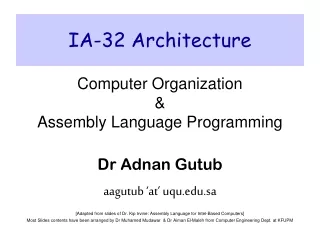
IA-32 Architecture Computer Organization and Assembly Language
Presentation Outline • Basic Computer Organization • Intel Microprocessors • IA-32 Registers • Instruction Execution Cycle • IA-32 Memory Management
data bus registers I/O I/O Processor (CPU) Memory Device Device #1 #2 ALU CU clock control bus address bus Basic Computer Organization • Since the 1940's, computers have 3 classic components: • Processor, called also the CPU (Central Processing Unit) • Memory and Storage Devices • I/O Devices • These components interconnected with one or more buses • Bus consists of • Data Bus • Address Bus • Control Bus
Processor • Processor consists of • Datapath • ALU • Registers • Control unit • ALU • Performs arithmetic and logic instructions • Control unit (CU) • Generates the control signals required to execute instructions • Implementation varies from one processor to another
Computer Buses • Common electrical pathway between multiple devices. • Internal to the CPU to transport data to and from the ALU • External to the CPU to connect it to main memory and I/O Controllers • The Bus Protocol is a well-defined set of rules governing how the bus works • Including mechanical and electrical specifications • All attached devices must obey these rules • Makes it possible for boards designed by third parties to be attached
Example buses • Multibus (Intel - 8086) • IBM PC (PC/XT) • ISA bus (PC/AT) • EISA bus (80386) • Microchannel (PS/2) • PCI bus (Many PCs) • Nubus (Macintosh) • Universal Serial Bus (modern PCs) • FireWire (Apple standard for high throughput – video/data)
Cycle 1 Cycle 2 Cycle 3 Clock • Synchronizes Processor and Bus operations • Clock cycle = Clock period = 1 / Clock rate • Clock rate = Clock frequency = Cycles per second • 1 Hz = 1 cycle/sec 1 KHz = 103 cycles/sec • 1 MHz = 106 cycles/sec 1 GHz = 109 cycles/sec • 2 GHz clock has a cycle time = 1/(2×109) = 0.5 nanosecond (ns) • Clock cycles measure the execution of instructions
Memory • Ordered sequence of bytes • The sequence number is called the memory address • Byte addressable memory • Each byte has a unique address • Supported by almost all processors • Physical address space • Determined by the address bus width • Pentium has a 32-bit address bus • Physical address space = 4GB = 232 bytes • Itanium with a 64-bit address bus can support • Up to 264 bytes of physical address space
Address Space Address Space is the set of memory locations (bytes) that can be addressed
Memory Unit • TwoControl Signals • Read • Write • Control whether memory should be read or written • Address Bus • Address is placed on the address bus • Address of location to be read/written • Data Bus • Data is placed on the data bus
Memory Read and Write Cycles • Read cycle 1. Processor places address on the address bus 2. Processor asserts the memory read control signal 3. Processor waits for memory to place the data on the data bus 4. Processor reads the data from the data bus • Processor drops the memory read signal • Write cycle 1. Processor places address on the address bus • Processor asserts the memory write control signal • Processor places the data on the data bus • Wait for memory to store the data (wait states for slow memory) 5. Processor drops the memory write signal
Reading from Memory • Multiple clock cycles are required • Memory responds much more slowly than the CPU • Address is placed on address bus • Read Line (RD) goes low, indicating that processor wants to read • CPU waits (one or more cycles) for memory to respond • Read Line (RD) goes high, indicating that data is on the data bus
Memory Devices • ROM = Read-Only Memory • Stores information permanently (non-volatile) • Used to store the information required to startup the computer • Many types: ROM, EPROM, EEPROM, and FLASH • FLASH memory can be erased electrically in blocks • RAM = Random Access Memory • Volatile memory: data is lost when device is powered off • Dynamic RAM (DRAM) • Inexpensive, used for main memory, must be refreshed constantly • Static RAM (SRAM) • Expensive, used for cache memory, faster access, no refresh • Video RAM (VRAM) • Dual ported: read port to refresh the display, write port for updates
registers cache memory lower cost per byte higher speed, smaller size main memory disk storage Memory Hierarchy • Registers • Fastest storage elements, stores most frequently used data • General-purpose registers: accessible to the programmer • Special-purpose registers: used internally by the microprocessor • Cache Memory • Fast SRAM that stores recently used instructions and data • Recent processors have 2 levels • Main Memory (DRAM) • Disk Storage • Permanent magnetic storage for files
Read/write head Sector Actuator Recording area Track 2 Track 1 Track 0 Arm Platter Direction of rotation Spindle Magnetic Disk Storage Disk Access Time = Seek Time + Rotation Latency + Transfer Time Seek Time: head movement to the desired track (milliseconds) Rotation Latency: disk rotation until desired sector arrives under the head Transfer Time: to transfer one sector
Example on Disk Access Time • Given a magnetic disk with the following properties • Rotation speed = 7200 RPM (rotations per minute) • Average seek = 8 ms, Sector = 512 bytes, Track = 200 sectors • Calculate • Time of one rotation (in milliseconds) • Average time to access a block of 32 consecutive sectors • Answer • Rotations per second • Rotation time in milliseconds • Average rotational latency • Time to transfer 32 sectors • Average access time = 7200/60 = 120 RPS = 1000/120 = 8.33 ms = time of half rotation = 4.17 ms = (32/200) * 8.33 = 1.33 ms = 8 + 4.17 + 1.33 = 13.5 ms
Input / Output Device (I/O device) Structure of I/O device • I/O device consists of 2 distinct parts: • I/O mechanism • I/O controller • I/O mechanism – the mechanical, electrical, and/ or optical components that make up this device • The I/O controller – manages the flow of information between I/O device and the computer
I/O Controllers • I/O devices are interfaced via an I/O controller • I/O controller uses the system bus to communicate with processor • I/O controller takes care of low-level operation details
I/O controllers ..cont • I/O controller consists of a buffer to temporarily hold the data being transferred td from the computer (processor) • It also accepts control signals (e.g START) from the computer and activates the proper I/O mechanism in response. • When I/O operation is complete, the I/O controller can transfer the contents of the buffer to the main memory of the computer. • It also return a set of control signals, e.g: DONE or ERROR – describing the status of the I/O operation just completed.
Examples of I/O Devices and I/O Controllers • I/O devices are the pieces of hardware, often outside the computer cabinet, • which perform input and output. Examples of I/O devices (typical interface formats in brackets) are: • modems and other serial devices (RS232 serial interface), • printers (parallel port interface) • disk drives (IDE, SCSI), • video monitors (analogue video signal), • and local area network cables and transceivers (high frequency serial signal). • The I/O controller used to connect a serial device to a computer is variously known as a UART (Universal Asynchronous Receiver Transmitter) and USART (Universal Synchronous and Asynchronous Receiver Transmitter)
I/O Techniques • Techniques for transferring data between I/O device and computer (processor) • Programmed I/O • Interrupt Driven I/O • I/O via DMA device
Programmed I/O • To activates the I/O process: • Processor issues a START command to begin the I/O operation. • Processor waits until the I/O controller issues a DONE signal, which means that the operation is finished. {at this time the data is in the buffer within the I/O controller or the processor} 3. (If input operation) Processor will check for error, and moves the data into the proper memory location if error is not found. • Disadvantageof this technique: The I/O operations are usually very slow in comparison with the internal speed of the computer. Computers execute instruction in s or ns, while I/O operations can take up to ms, sec or even minutes to complete. This is inefficient as the processor will stay idle waiting for the I/O operations to complete.
Interrupt-Driven I/O • Issue START command for I/O operation . • Processor now free to handle other computations • When interrupt signal occurs, telling the processor that the I/O is done, stop whatever it is doing. • Move data to the memory. • Advantage: No waiting or wasted time except the overhead time needed for servicing the interrupt. • Disadvantage: Both programmed I/O and interrupt-driven I/O – in both cases the processor is responsible for transferring of data into the memory because the only path into the memory is through the processor.
I/O via DMA device • To start I/O operation: • Load the memory address of the buffer into the I/O controller • Issue START command to initiate the I/O operation. • The DMA controller transfers an entire physical record directly into the specified memory addresses. • The processor is interrupted when the entire physical record has been transferred and the I/O operation is completed,
What happened when an interrupt occurs? • An interrupt is a signal to the processor that a specific event has occurred. • The processor will perform the following: • Interrupts the task, T that is currently executing. • Saves the state of the machine (registers, memory, etc ) so that T can be restarted at a later time. • Checks to see what event caused the interrupt. • Executes a special program associated with this specific event (called an interrupt handler). • When the interrupt handler is finished, restores the state of the machine to its pre-interrupted conditions. • Restarts task T from exactly the point at which it was interrupted.
Intel Microprocessors • Intel introduced the 8086 microprocessor in 1979 • 8086, 8087, 8088, and 80186 processors • 16-bit processors with 16-bit registers • 16-bit data bus and 20-bit address bus • Physical address space = 220 bytes = 1 MB • 8087 Floating-Point co-processor • Uses segmentation and real-address mode to address memory • Each segment can address 216 bytes = 64 KB • 8088 is a less expensive version of 8086 • Uses an 8-bit data bus • 80186 is a faster version of 8086
Intel 80286 and 80386 Processors • 80286 was introduced in 1982 • 24-bit address bus 224 bytes = 16 MB address space • Introduced protected mode • Segmentation in protected mode is different from the real mode • 80386 was introduced in 1985 • First 32-bit processor with 32-bit general-purpose registers • First processor to define the IA-32 architecture • 32-bit data bus and 32-bit address bus • 232 bytes 4 GB address space • Introduced paging, virtual memory, and the flat memory model • Segmentation can be turned off
Intel 80486 and Pentium Processors • 80486 was introduced 1989 • Improved version of Intel 80386 • On-chip Floating-Point unit (DX versions) • On-chip unified Instruction/Data Cache (8 KB) • Uses Pipelining: can execute up to 1 instruction per clock cycle • Pentium (80586) was introduced in 1993 • Wider 64-bit data bus, but address bus is still 32 bits • Two execution pipelines: U-pipe and V-pipe • Superscalar performance: can execute 2 instructions per clock cycle • Separate 8 KB instruction and 8 KB data caches • MMX instructions (later models) for multimedia applications
Intel P6 Processor Family • P6 Processor Family: Pentium Pro, Pentium II and III • Pentium Pro was introduced in 1995 • Three-way superscalar: can execute 3 instructions per clock cycle • 36-bit address bus up to 64 GB of physical address space • Introduced dynamic execution • Out-of-order and speculative execution • Integrates a 256 KB second level L2 cache on-chip • Pentium II was introduced in 1997 • Added MMX instructions (already introduced on Pentium MMX) • Pentium III was introduced in 1999 • Added SSE instructions and eight new 128-bit XMM registers
Pentium 4 and Xeon Family • Pentium 4 is a seventh-generation x86 architecture • Introduced in 2000 • New micro-architecture design called Intel Netburst • Very deep instruction pipeline, scaling to very high frequencies • Introduced the SSE2 instruction set (extension to SSE) • Tuned for multimedia and operating on the 128-bit XMM registers • In 2002, Intel introduced Hyper-Threading technology • Allowed 2 programs to run simultaneously, sharing resources • Xeon is Intel's name for its server-class microprocessors • Xeon chips generally have more cache • Support larger multiprocessor configurations
Pentium-M and EM64T • Pentium M (Mobile) was introduced in 2003 • Designed for low-power laptop computers • Modified version of Pentium III, optimized for power efficiency • Large second-level cache (2 MB on later models) • Runs at lower clock than Pentium 4, but with better performance • Extended Memory 64-bit Technology (EM64T) • Introduced in 2004 • 64-bit superset of the IA-32 processor architecture • 64-bit general-purpose registers and integer support • Number of general-purpose registers increased from 8 to 16 • 64-bit pointers and flat virtual address space • Large physical address space: up to 240 = 1 Terabytes
CISC and RISC • CISC – Complex Instruction Set Computer • Large and complex instruction set • Variable width instructions • Requires microcode interpreter • Each instruction is decoded into a sequence of micro-operations • Example: Intel x86 family • RISC – Reduced Instruction Set Computer • Small and simple instruction set • All instructions have the same width • Simpler instruction formats and addressing modes • Decoded and executed directly by hardware • Examples: ARM, MIPS, PowerPC, SPARC, etc.
32-bit General-Purpose Registers EAX EBP EBX ESP ECX ESI EDX EDI 16-bit Segment Registers EFLAGS CS ES SS FS EIP DS GS Basic Program Execution Registers • Registers are high speed memory inside the CPU • Eight 32-bit general-purpose registers • Six 16-bit segment registers • Processor Status Flags (EFLAGS) and Instruction Pointer (EIP)
General-Purpose Registers • Used primarily for arithmetic and data movement • mov eax, 10 move constant 10 into register eax • Specialized uses of Registers • EAX – Accumulator register • Automatically used by multiplication and division instructions • ECX – Counter register • Automatically used by LOOP instructions • ESP – Stack Pointer register • Used by PUSH and POP instructions, points to top of stack • ESI and EDI – Source Index and Destination Index register • Used by string instructions • EBP – Base Pointer register • Used to reference parameters and local variables on the stack
Accessing Parts of Registers • EAX, EBX, ECX, and EDX are 32-bit Extended registers • Programmers can access their 16-bit and 8-bit parts • Lower 16-bit of EAX is named AX • AX is further divided into • AL = lower 8 bits • AH = upper 8 bits • ESI, EDI, EBP, ESP have only 16-bit names for lower half
Special-Purpose & Segment Registers • EIP = Extended Instruction Pointer • Contains address of next instruction to be executed • EFLAGS = Extended Flags Register • Contains status and control flags • Each flag is a single binary bit • Six 16-bit Segment Registers • Support segmented memory • Six segments accessible at a time • Segments contain distinct contents • Code • Data • Stack
EFLAGS Register • Status Flags • Status of arithmetic and logical operations • Control and System flags • Control the CPU operation • Programs can set and clear individual bits in the EFLAGS register
Status Flags • Carry Flag • Set when unsigned arithmetic result is out of range • Overflow Flag • Set when signed arithmetic result is out of range • Sign Flag • Copy of sign bit, set when result is negative • Zero Flag • Set when result is zero • Auxiliary Carry Flag • Set when there is a carry from bit 3 to bit 4 • Parity Flag • Set when parity is even • Least-significant byte in result contains even number of 1s
Floating-Point, MMX, XMM Registers • Floating-point unit performs high speed FP operations • Eight 80-bit floating-point data registers • ST(0), ST(1), . . . , ST(7) • Arranged as a stack • Used for floating-point arithmetic • Eight 64-bit MMX registers • Used with MMX instructions • Eight 128-bit XMM registers • Used with SSE instructions
Instruction Fetch Obtain instruction from program storage Instruction Decode Determine required actions and instruction size Operand Fetch Infinite Cycle Locate and obtain operand data Execute Compute result value and status Writeback Result Deposit results in storage for later use Basic Instruction Execute Cycle
PC program I1 I2 I3 I4 . . . fetch memory read op1 op2 registers registers instruction I1 register decode write write ALU flags execute (output) Instruction Execution Cycle – cont'd • Instruction Fetch • Instruction Decode • Operand Fetch • Execute • Result Writeback
Some Important Questions to Ask • The exact sequence of events during an instruction cycle depends on the design of the CPU. Assume a CPU has MAR, MBR, IP and IR. The control unit of the CPU also issues Read, Write, and Execute control signals. Give the steps of action if the instruction ADD AX, CX is fetched from the memory and executed by the CPU. Also specify the control signals involved.
Some Important Questions to Ask • The exact sequence of events during an instruction cycle depends on the design of the CPU. Assume a CPU has MAR, MBR, IP and IR. The control unit of the CPU also issues Read, Write, and Execute control signals. Give the steps of action if the instruction ADD BX, SUM is fetched from the memory and executed by the CPU. Also specify the control signals involved.