Download
1 / 16
160 likes | 517 Views
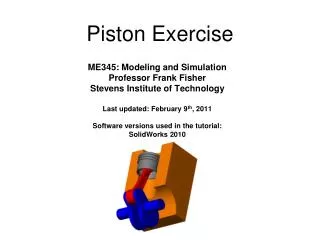
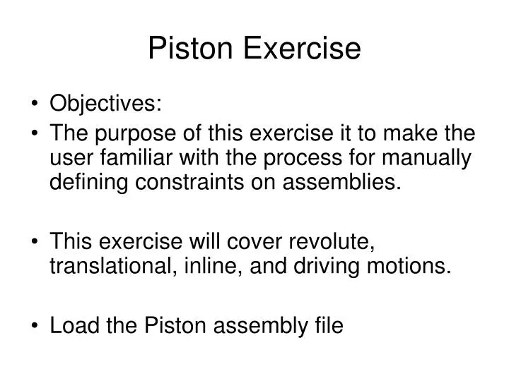
Piston Exercise. Objectives: The purpose of this exercise it to make the user familiar with the process for manually defining constraints on assemblies. This exercise will cover revolute, translational, inline, and driving motions. Load the Piston assembly file. Piston Exercise.

E N D
Piston Exercise • Objectives: • The purpose of this exercise it to make the user familiar with the process for manually defining constraints on assemblies. • This exercise will cover revolute, translational, inline, and driving motions. • Load the Piston assembly file
Piston Exercise Piston.sldasm
Piston Model Exercise *Make ENGINEBLOCK ground* *Make all other parts moving* PARTS SHOULD BE DEFINED AS FOLLOWS:
Piston Model Exercise Define Revolute Joint for Crankshaft to Ground
Piston Model Exercise Define Revolute Joint for Crankshaft to Conrod 2 1 3
Piston Model Exercise Define Inline JPrim Joint for Piston to Conrod 2 1 3 4
Piston Model Exercise Define Translational Joint for Piston to Engine Block 2 1 3
Piston Model Exercise Define 360 Deg/sec Rotary Motion on Crankshaft Revolute
Piston Model Exercise Run the Simulation (using defaults)
Joint Definition - Motion Depending on the joint type, you can control different freedoms Can control the displacement, velocity, or acceleration of a joint You can select from Input Functions: Constant Step Harmonic Spline Expression
Joint Definition - Motion with Step Function 112.50 90.00 67.50 Displacement (deg) 45.00 22.50 0.00 -22.50 -1.00 -0.70 -0.40 -0.10 0.20 0.50 0.80 1.10 1.40 1.70 2.00 Time (s)
67.50 45.00 22.50 0.00 Displacement (deg) -22.50 -45.00 -67.50 0.00 0.50 1.00 1.50 2.00 2.50 3.00 3.50 4.00 4.50 5.00 Time (s) Joint Definition - Motion with Harmonic Function
33.75 56.25 22.50 45.00 11.25 33.75 22.50 0.00 Displacement (deg) Displacement (deg) 11.25 -11.25 0.00 -22.50 -11.25 -33.75 0.00 0.50 1.00 1.50 2.00 2.50 3.00 3.50 4.00 4.50 5.00 0.00 0.50 1.00 1.50 2.00 2.50 3.00 3.50 4.00 4.50 5.00 Time (s) Time (s) Joint Definition - Motion with Harmonic Function With a 0.25-sec time offset only or with a 90 degree phase offset (same result) Harmonic function with 22.5º average offset (same amount as amplitude)
100 100 80 80 Overshoot Data Points 60 60 40 40 20 20 0 0 -20 0 1 2 3 4 0 1 2 3 4 Joint Definition - Motion with Data Points As you cannot have any instantaneous sharp transitions on motion generators, two spline-fitting options are available to smooth out the data. This will have little effect on smooth transitioning functions but will change behavior on functions like that shown below. The Data ID allows the user to store several data point functions and select the one they wish to edit or use for a specific motion generator.
Plotting Results in SolidWorks Inter Plot Options are available by right clicking on a motion entity. The pop-up menu is entity sensitive so will only show relevant plot options.
Plotting Results in SolidWorks Motion Entities can also be dragged directly onto the plot branch. Then the user can select the result and component they wish to display. Note that Results with a CM at the front are for the Center of Mass location and all other results on parts are measured at the Part Reference Frame origin. Joint Results for Force are in the global coordinate system. All joint displacement, velocity, and accelerations are in the joint coordinate system.