Download
1 / 25
260 likes | 469 Views
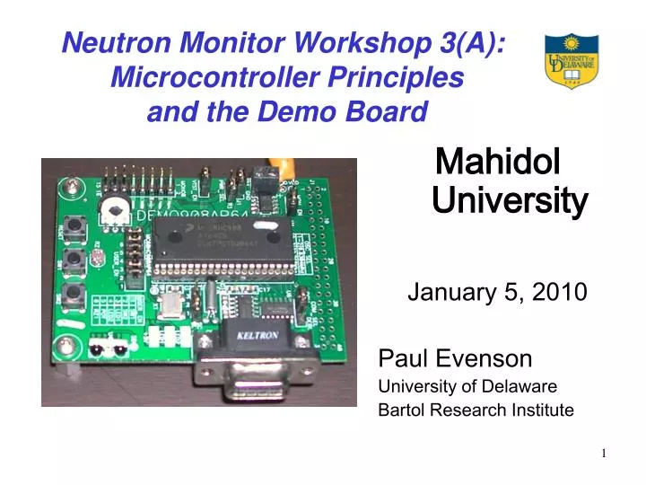
Neutron Monitor Workshop 3(A): Microcontroller Principles and the Demo Board. Mahidol University January 5, 2010 Paul Evenson University of Delaware Bartol Research Institute. Workshop Series Idea. Introduce students to technical aspects of neutron monitor operation

E N D
Neutron Monitor Workshop 3(A): Microcontroller Principles and the Demo Board Mahidol University January 5, 2010 Paul Evenson University of Delaware Bartol Research Institute
Workshop Series Idea • Introduce students to technical aspects of neutron monitor operation • Rotating workshop series that will repeat every two years at a two per year rate • Independent enough so students can join at any point • Accommodate wide skill range with an emphasis on “hands on” experience and individual discussion
Workshop Series Plan • Detector operation • Detector Physics and Analog Electronics • Art and Science of Soldering • Digital Circuits • Principles of Digital Logic • Neutron Monitor Digital Electronics • Microcontrollers • Principles and the Demo Board • Next Generation Readout Board • Real time data acquisition • Principles of Telemetry and Data Acquisition • Data Conversion and Manipulation with Visual Basic
Plan For Today • Lecture with Demonstrations • Discuss Microcontrollers • Explain DEMO8 Board • Explain Code Warrior • Demonstrate Simple Program • Individual work on programs • Several CodeWarrior stations • Only one DEMO8 board • Take turns to test
Microcomputer Very fast (GHz) Powerful Instructions Manage large memory High speed general data pathways Often a “chip set” Expensive ($100’s) Microcontroller Modest speed (10Mhz) Simple instructions Small memory (mainly ROM) I/O to communicate with logic Typically single chip Cheap ($5) Microcomputer vs. Microcontroller
FPGA Very fast (GHz) No fixed instructions No fixed memory No structured I/O Often has a microcomputer on same chip Expensive ($100’s) Microcontroller Modest speed (10Mhz) Simple instructions Small memory (mainly ROM) I/O to communicate with logic Typically single chip Cheap ($5) FPGA vs. Microcontroller
Essence of a Microcontroller:MC68HC908AP64 • All pins either sense or produce (and most can do either) digital logic levels under control of the internal program
Behind This Innocent Exterior Lurks A Complex Mind! • In addition to the straightforward input output lines there are functions to construct timing patterns and to communicate in standard ways with other devices • All of this is under the control of the program stored in ROM (Read Only Memory)
Computer Operating system converts “user friendly” code into internal instructions Operating system loads the program into RAM (supplemented by virtual memory on disk) Operating system manages data flow into and out of the program Operating system manages execution and terminates runaway programs Microcontroller Separate system on a computer (Code Warrior) converts “user friendly” code into internal instructions Hardware device (MON08 Multilink) stores the program in ROM on the chip All I/O is under direct program control Limited protection against program faults Programming (I)
Programming (II) • Code Warrior in fact has the capability to interpret high level languages (C++) • Common functions can be captured in subroutines and linked into a program • I will however stick to the simplest kind of programming (assembly language) where each line of code translates to a specific machine instruction
“Stored Program” Computer • Memory • Series of locations each with an address • MC68HC908AP64 uses 8-bit bytes • Contain binary bit patterns • Program and data are intermixed • Program Counter • Points to the memory location containing the next instruction • Registers • Special memory locations implicitly referenced by instructions
Computer Instruction Cycle • Fetch the Instruction Pointed to by Program Counter • Instructions can be several bytes long • First byte of the instruction gives length • Execute the Instruction • Modify memory and/or registers as specified by the instruction • Set Condition Codes • Usually indicate whether a result is +/0/- • Update PC to location of next instruction • Can be as simple as n+1 • Often based on instruction and condition codes
Some Registers are Part of the Memory Map, and are Accessed Like Data
CPU Registers are Not Part of the Memory Map; In a Microcontroller They Are Very Simple
Accumulator and Index Register • The accumulator is a general-purpose 8-bit register. • The CPU uses the accumulator to hold operands and the results of arithmetic/logic operations. • The 16-bit index register allows indexed addressing of a 64-Kbyte memory space. H is the upper byte of the index register, and X is the lower byte. H:X is the concatenated 16-bit index register. • In the indexed addressing modes, the CPU uses the contents of the index register to determine the conditional address of the operand. • The index register can serve also as a temporary data storage location.
Program Counter • The program counter is a 16-bit register that contains the address of the next instruction or operand to be fetched. • Normally, the program counter automatically increments to the next sequential memory location every time an instruction or operand is fetched. • Jump, branch, and interrupt operations load the program counter with an address other than that of the next sequential location. • During reset, the program counter is loaded with the reset vector address located at $FFFE and $FFFF. • The vector address is the address of the first instruction to be executed after exiting the reset state.
The Stack • The “stack” is a group of memory locations specially arranged to allow quick storage and retrieval of temporary data. • The latest entry placed on the stack is the first to be removed • Primarily this is used to store return addresses for multiple layers of subroutines • The stack pointer is a 16-bit register that contains the address of the next location on the stack. • During a reset, the stack pointer is preset to $00FF. • The reset stack pointer (RSP) instruction sets the least significant byte to $FF and does not affect the most significant byte. • The stack pointer decrements as data are pushed onto the stack and increments as data are pulled from the stack.
Condition Code Register • The 8-bit condition code register contains the interrupt mask and five flags that indicate the results of the instruction just executed. Bits 6 and 5 are set permanently to logic 1. The five logic flags are: • The CPU sets the overflow flag when a two's complement overflow occurs. The signed branch instructions BGT, BGE, BLE, and BLT use the overflow flag. • The CPU sets the half-carry flag when a carry occurs between accumulator bits 3 and 4 during an add-without-carry (ADD) or add-with-carry (ADC) operation. The half-carry flag is required for binary-coded decimal (BCD) arithmetic operations. The DAA instruction uses the states of the H and C flags to determine the appropriate correction factor. • The CPU sets the negative flag when an arithmetic operation, logic operation, or data manipulation produces a negative result, setting bit 7 of the result. • The CPU sets the zero flag when an arithmetic operation, logic operation, or data manipulation produces a result of $00. • The CPU sets the carry/borrow flag when an addition operation produces a carry out of bit 7 of theaccumulator or when a subtraction operation requires a borrow. Some instructions — such as bit test and branch, shift, and rotate — also clear or set the carry/borrow flag.
DEMO908AP64 Board • Carries a sample MC68HC908AP64 • Several simple peripherals • Connection to other circuits
Code Warrior and the MON08 USB Multilink Interface • The development environment CodeWarrior and the USB Multilink together allow construction and testing of programs for the microcontroller.
Functions of the Development System • Assembler/Compiler • Manages user code • Adds processor description • Linker • Combines several compiled programs • Adds further processor information • Loader • Transfers the program to the chip • Debugger • Allows step by step execution of code • Not all that useful for realtime stuff
Demonstration • First I will demonstrate a small program that flashes patterns of lights on the Demo board • Then we can either jointly try to make it do something different, or you can have your own copies to use CodeWarrior on different machines. • To test the programs we must use the copy of Code Warrior linked to the Demo board