Download
1 / 19
200 likes | 344 Views
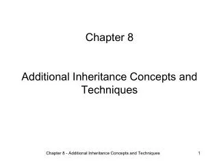
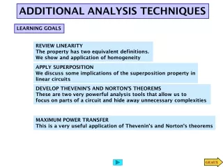
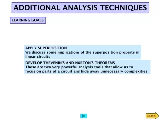
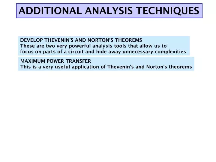
ADDITIONAL ANALYSIS TECHNIQUES. DEVELOP THEVENIN’S AND NORTON’S THEOREMS These are two very powerful analysis tools that allow us to focus on parts of a circuit and hide away unnecessary complexities. MAXIMUM POWER TRANSFER This is a very useful application of Thevenin’s and Norton’s theorems.

E N D
ADDITIONAL ANALYSIS TECHNIQUES DEVELOP THEVENIN’S AND NORTON’S THEOREMS These are two very powerful analysis tools that allow us to focus on parts of a circuit and hide away unnecessary complexities MAXIMUM POWER TRANSFER This is a very useful application of Thevenin’s and Norton’s theorems
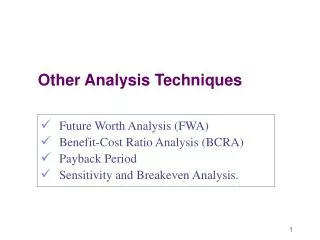
THEVENIN’S AND NORTON’S THEOREMS These are some of the most powerful analysis results to be discussed. They permit to hide information that is not relevant and concentrate in what is important to the analysis
From PreAmp (voltage ) To speakers REPLACE AMPLIFIER BY SIMPLER “EQUIVALENT” TO MATCH SPEAKERS AND AMPLIFIER IT IS MUCH EASIER TO CONSIDER THIS EQUIVALENT CIRCUIT! Low distortion audio power amplifier TO MATCH SPEAKERS AND AMPLIFIER ONE SHOULD ANALYZE THIS CIRCUIT Courtesy of M.J. Renardson http://angelfire.com/ab3/mjramp/index.html
Thevenin Equivalent Circuit for PART A THEVENIN’S EQUIVALENCE THEOREM
Norton Equivalent Circuit for PART A NORTON’S EQUIVALENCE THEOREM
1. Because of the linearity of the models, for any Part B the relationship between Vo and the current, i, has to be of the form 3. If part B is an open circuit then i=0 and... OUTLINE OF PROOF 2. Result must hold for “every valid Part B” that we can imagine 4. If Part B is a short circuit then Vo is zero. In this case
For ANY circuit in Part B The voltage source is called the THEVENIN EQUIVALENT SOURCE The resistance is called the THEVENIN EQUIVALENT RESISTANCE PART A MUST BEHAVE LIKE THIS CIRCUIT THEVENIN APPROACH This is the Thevenin equivalent circuit for the circuit in Part A
Norton Norton Approach
Thevenin Norton ANOTHER VIEW OF THEVENIN’S AND NORTON’S THEOREMS This equivalence can be viewed as a source transformation problem It shows how to convert a voltage source in series with a resistor into an equivalent current source in parallel with the resistor SOURCE TRANSFORMATION CAN BE A GOOD TOOL TO REDUCE THE COMPLEXITY OF A CIRCUIT
EXAMPLE: SOLVE BY SOURCE TRANSFORMATION In between the terminals we connect a current source and a resistance in parallel The equivalent current source will have the value 12V/3k The 3k and the 6k resistors now are in parallel and can be combined In between the terminals we connect a voltage source in series with the resistor The equivalent source has value 4mA*2k The 2k and the 2k resistor become connected in series and can be combined After the transformation the sources can be combined The equivalent current source has value 8V/4k and the combined current source has value 4mA Options at this point 1. Do another source transformation and get a single loop circuit 2. Use current divider to compute I_0 and then compute V_0 using Ohm’s law
One circuit problem 1. Determine the Thevenin equivalent source Remove part B and compute the OPEN CIRCUIT voltage Second circuit problem Remove part B and compute the SHORT CIRCUIT current 2. Determine the SHORT CIRCUIT current A General Procedure to Determine the Thevenin Equivalent
NODE ANALYSIS When the current source is open the current through the short circuit is When the voltage source is set to zero, the current through the short circuit is To compute the Thevenin resistance we use AN EXAMPLE OF DETERMINING THE THEVENIN EQUIVALENT Part B is irrelevant. The voltage V_ab will be the value of the Thevenin equivalent source. What is an efficient technique to compute the open circuit voltage? Now for the short circuit current Lets try source superposition For this case the Thevenin resistance can be computed as the resistance from a - b when all independent sources have been set to zero
“Part B” “Part B” Determining the Thevenin Equivalent in Circuits with Only INDEPENDENT SOURCES The Thevenin Equivalent Source is computed as the open loop voltage The Thevenin Equivalent Resistance CAN BE COMPUTED by setting to zero all the sources and then determining the resistance seen from the terminals where the equivalent will be placed Since the evaluation of the Thevenin equivalent can be very simple, we can add it to our toolkit for the solution of circuits!!
EXAMPLE COMPUTE Vo USING THEVENIN For open loop voltage use KVL In the region shown, one could use source transformation twice and reduce that part to a single source with a resistor. ... Or we can apply Thevenin Equivalence to that part (viewed as “Part A”) For the open loop voltage the part outside the region is eliminated The original circuit becomes... And one can apply Thevenin one more time! ...and we have a simple voltage divider!!
For the Thevenin resistance “Part B” Or we can use Thevenin only once to get a voltage divider Contribution of the voltage source Contribution of the current source For the Thevenin voltage we have to analyze the following circuit METHOD?? Source superposition, for example Thevenin Equivalent of “Part A” Simple Voltage Divider
PART B PART B COMPUTE Vo USING NORTON COMPUTE Vo USING THEVENIN
From PreAmp (voltage ) To speakers BASIC MODEL FOR THE ANALYSIS OF POWER TRANSFER MAXIMUM POWER TRANSFER Courtesy of M.J. Renardson http://angelfire.com/ab3/mjramp/index.html The simplest model for a speaker is a resistance...
3 MAXIMUM POWER TRANSFER For every choice of R_L we have a different power. How do we find the maximum value? Consider P_L as a function of R_L and find the maximum of such function Set the derivative to zero to find extreme points. For this case we need to set to zero the numerator The maximum power transfer theorem The value of the maximum power that can be transferred is The load that maximizes the power transfer for a circuit is equal to the Thevenin equivalent resistance of the circuit. ONLY IN THIS CASE WE NEED TO COMPUTE THE THEVENIN VOLTAGE