Download
1 / 12
270 likes | 1.35k Views
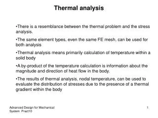
Module 7. Thermal-Stress Analysis. Thermal-Stress Analysis. In this chapter, we will briefly describe how to do a thermal-stress analysis. The purpose is two-fold: To show you how to apply thermal loads in a stress analysis. To introduce you to a coupled-field analysis. Topics covered:

E N D
Module 7 Thermal-Stress Analysis
Thermal-Stress Analysis • In this chapter, we will briefly describe how to do a thermal-stress analysis. • The purpose is two-fold: • To show you how to apply thermal loads in a stress analysis. • To introduce you to a coupled-field analysis. • Topics covered: A. Overview B. Sequential C. Direct D. Workshop January 30, 2001 Inventory #001441 7-2
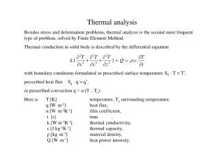
Thermal-Stress AnalysisA. Overview Thermally Induced Stress • When a structure is heated or cooled, it deforms by expanding or contracting. • If the deformation is somehow restricted — by displacement constraints or an opposing pressure, for example — thermal stresses are induced in the structure. • Another cause of thermal stresses is non-uniform deformation, due to different materials (i.e, different coefficients of thermal expansion). Thermal stresses due to constraints Thermal stresses due to different materials January 30, 2001 Inventory #001441 7-3
Thermal-Stress Analysis…Overview • There are two methods of solving thermal-stress problems using ANSYS. Both methods have their advantages. • Sequential coupled field • Older method, uses two element types mapping thermal results as structural temperature loads • Efficient when running many thermal transient time points but few structural time points • Can easily be automated with input files • Direct coupled field • Newer method uses one element type to solve both physics problems • Allows true coupling between thermal and structural phenomena • May carry unnecessary overhead for some analyses January 30, 2001 Inventory #001441 7-4
The Sequential method involves two analyses: 1. First do a steady-state (or transient) thermal analysis. Model with thermal elements. Apply thermal loading. Solve and review results. 2. Then do a static structural analysis. Switch element types to structural. Define structural material properties, including thermal expansion coefficient. Apply structural loading, including temperatures from thermal analysis. Solve and review results. Thermal Analysis jobname.rth Temperatures Structural Analysis jobname.rst Thermal-Stress AnalysisB. Sequential Method January 30, 2001 Inventory #001441 7-5
Thermal-Stress Analysis…Sequential Method 1. Thermal Analysis • The procedure for this is described in Chapter 6. 2. Structural Analysis a) Move to PREP7 and switch element types from thermal to structural. • Preprocessor > Element Type > Switch Elem Type • Or ETCHG command Caution: Switching element types will reset all element options back to their default settings. For example, if you used 2-D axisymmetric elements in the thermal analysis, you may need to respecify the axisymmetric option after the switch. Therefore, be sure to verify and set the proper element options: • Preprocessor > Element Type > Add/Edit/Delete > [Options] • Or use ETLIST and KEYOPT commands January 30, 2001 Inventory #001441 7-6
Thermal-Stress Analysis…Sequential Method b) Define structural material properties (EX, etc.), including the coefficient of thermal expansion (ALPX). (If you use the ANSYS-supplied material library, both thermal and structural properties will be defined, so this step may not be needed.) Note: If ALPX is not defined or set to zero, no thermal strains will be calculated. You can use this technique to “turn off” temperature effects! c) Specify static analysis type. This step is needed only if the thermal analysis was a transient. • Solution > -Analysis Type- New Analysis • Or ANTYPE command January 30, 2001 Inventory #001441 7-7
Thermal-Stress Analysis…Sequential Method d) Apply structural loads and include temperatures as part of the loading. • Solution > -Loads- Apply > -Structural- Temperature > From Therm Analy • Or use the LDREAD command. e) Solve. f) Review stress results. January 30, 2001 Inventory #001441 7-8
The Direct Method usually involves just one analysis that uses a coupled-field element type containing all necessary degrees of freedom. 1. First prepare the model and mesh using one of the following coupled field element types. PLANE13 (plane solid). SOLID5 (hexahedron). SOLID98 (tetrahedron). Apply both the structural and thermal loads and constraints to the model. Solve and review both thermal and structural results. Thermal Analysis Combined Structural Analysis jobname.rst Thermal-Stress AnalysisC. Direct Method January 30, 2001 Inventory #001441 7-9
Sequential For coupling situations which do not exhibit a high degree of nonlinear interaction, the sequential method is more efficient and flexible because you can perform the two analyses independently of each other. In a sequential thermal-stress analysis, for example, you can perform a nonlinear transient thermal analysis followed by a linear static stress analysis. You can then use nodal temperatures from ANY load step or time-point in the thermal analysis as loads for the stress analysis. Direct Direct coupling is advantageous when the coupled-field interaction is highly nonlinear and is best solved in a single solution using a coupled formulation. Examples of direct coupling include piezoelectric analysis, conjugate heat transfer with fluid flow, and circuit-electromagnetic analysis. Thermal-Stress Analysis… Sequential vs. Direct January 30, 2001 Inventory #001441 7-10
Thermal-Stress AnalysisD. Workshop • Refer to your Workshop Supplement for instructions on: W4a. Axisymmetric Pipe with Fins (Sequential Coupled Fileld) W4b. Axisymmetric Pipe with Fins (Direct Coupled Field) January 30, 2001 Inventory #001441 7-11