Download
1 / 13
150 likes | 321 Views
Mathematical Engineering in Avionics Applications. Dr. SK Chaudhuri Sc. ‘H’ Associate Director, RCI. 9 th June 2007, IISc Bangalore. FUNCTIONAL BLOCK DIAGRAM OF MAJOR MISSILE SUBSYSTEMS. Reference Generation System. Guidance Command. Acceleration Rates.

E N D
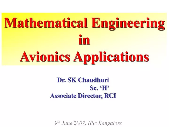
Mathematical Engineering in Avionics Applications Dr. SK Chaudhuri Sc. ‘H’ Associate Director, RCI 9th June 2007, IISc Bangalore
FUNCTIONAL BLOCK DIAGRAM OF MAJOR MISSILE SUBSYSTEMS Reference Generation System Guidance Command Acceleration Rates Target Trajectory Knowledge Gathering system Decision Process Action Process Airframe & Propulsion Kinematics Missile Trajectory KNOWLEDGE GATHERING SYSTEM: Navigation process for position, velocity and attitude etc. DECISION PROCESS: Missile guidance system based on available knowledge and stored guidance (if required) ACTION PROCESS: Flight control system with sensors, actuators X Vx ~ ~ ~ ~ M/T
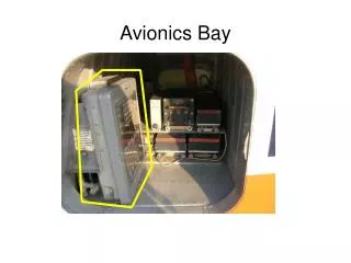
Engine Bay Control Surface Radome Electronic Bay Wing Nose Cone Guidance & Control System Warhead Propellant Tank MISSILE CONFIGURATION Reference Generation system Rates & Acceleration Navigation Computer Guidance System Autopilot Actuation System Airframe & Propulsion Sensors Inertial Sensors Target Trajectory RF/IR Sensors Kinematics Missile Trajectory ~
~ MATHEMATICAL ENGINEERING INVOLVED MISSILE SUBSYSTEMS • Dynamic Eqn.s with Newton’s laws of motion • Fluid dynamics • Nonlinear Time varying differential Eqn.s • Numerical Integration (Euler & RK4) • Interpolation • Flexibility dynamics in terms of generalized coordinates • Estimation Theory • Random & Stochastic Process • State space Methods • Matrix algebra • Iteration Techniques • Interpolation • Optimization Tech. • Laplace Transforms • Z-Transforms • State space Methods • Optimization Tech. • Robust Design • Quaternion algebra • Matrix algebra • Integration techniques • Solid geometry with Geodetic, Geocentric and 3D representation Rates & Acceleration Navigation Computer Guidance System Autopilot Actuation System Airframe & Propulsion • Curve Fitting • Filtering techniques. • Fast Fourier Transforms • Signal Processing • Filtering techniques. Sensors Inertial Sensors Target Trajectory RF/IR Sensors Kinematics Missile Trajectory • Kinematic Equations • Linear and Matrix Algebra • Integrations techniques
Mathematical Modelling And Simulation ACTUAL SYSTEM VALIDATION COMPARISON MATH MODEL COMPUTER SIMULATION COMPARISON VERIFICATION System, Model & Simulation Correlation • BASIC TECH. COMPONENTS : • Requirements which final Simulation must satisfy. • Equations for representing actual system. • Program Equations for Simulation. • Compare Simulation Program to the Model and modify the mistakes. • Compare Simulation result with actual results. • VERIFICATION : • Process to determine that a program causes computer to operate as intended by the software designer (i.e. Equations are programmed correctly). • VALIDATION : • Process to determine that computer simulation behaves like actual system in all pertinent respects.
Qm T R VB=([DCM] ) S ROTATIONAL AND TRANSLATIONAL LOOP JOB ALLOCATION IN REAL TIME MISSILE 6DOF axs axs = (Tx-Dx)/ M ays = Y /M+Yy /M +cr azs = Z /M+Zp /M -cq ays azs p p INCREMENTAL ANGLES AND VELOCITIES p = Lpp/Ixx+LRR /Ixx+ClQs/Ixx q = M /Iyy+Mp /Iyy r = N /Izz+Ny /Izz q q r r U A/D & INERTIAL PARAMETERS =tan-1(W/U) =tan-1(V/U) VM=(U2+V2+W2 ) VX QUAT UPDATE ENGINE THRUST 1-3 NAV. FUNC V VR DCM W VB1-3 t Vm Z
TWD EFFECTS IN 6-DOF MODEL • Undue Roll oscillations due to low damping introduced by gimballed engines, thrust frame and hardware actuator compliance
MISSILE AUTOPILOT WITH FLEXIBILITY Unstable Autopilot Response Modified Stable Autopilot Response
TRANSFER ALIGNMENT (TA) SCHEME FOR SHIP LAUNCHED MISSILE GPS/DGPS LOG : S System Slave Accn Master Vel, Lat, Long Master INS update F Meas & Noise s ^ States - Ship 100/s SS Process Noise AKF + 2 0.15 m/s (Adaptive Fdbks Kalman Filter) Slave INS Missile S curve Þ q, r 1.2 0 /s Slave Vel, Lat, Long Þ (SDINS) Feed back Conversion to Controller Alignment Error quaternion corrections PII-06 Launch TA Results • Demonstrated 7-state AKF based TA for SSMs launched from Moving Platform. • Fdbk gains are selected using Linear Quadratic Gaussian Regulator and offline Matrix Riccati equation solution. • Integrated the above with EKF based GPS-INS data fusion for Dhanush extended range missions. • Validated through Van, Aircraft, Ship & Flight trials. Blue = Optically measured syi error red = AKF estimated syi error Time (sec)
Pos, Vel, DCM GPS-INS DATA FUSION SCHEME FOR EXT. RANGE PRITHVI MISSION LC PURE NAVIGATION Nominal Trajectory Quat, Pos, Vel GUIDANCE MODULE Rates Accln IMU Pos, Vel FUSED NAVIGATION Corrections Quaternion Guidance Commands TVC ADC KF MODULE Defln Defln GPS GPS Data CONTROL ACTUATION SYSTEM • Demonstrated 17-state Extended Kalman Filter (EKF) based GPS-INS Data Fusion in OBC for extended range Prithvi missions.
NUMBER OF FLIGHT TRIALS OF PRITHVI 64 Prithvi (Planned) No. of Flight Trials 38 (Planned) 12 (Actual) 0 1996 2004 1984 1988 Year • Requirement of number of flight trials is reduced because of HILS.