Download
1 / 28
280 likes | 284 Views
Learn about graphical models and their importance in system development. Understand the different types of models and diagrams used, their language and syntax, and the concepts they represent.

E N D
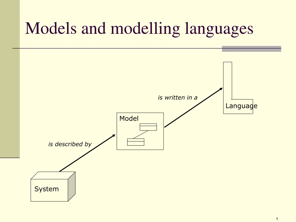
Model Models and modelling languages is written in a Language is described by System
The reality – three levels People carrying out manual activities Peolpe interacting with computers Computers carrying out automatic activities
The reality and models – three levels Business processes (in Activity Diagram) Communication between people (in Sequence Diagram) Business concepts (in Class Diagram) Use Case Activity Diagram Sequence Diagram Information Model (in Class Diagram) The reality Graphical models/diagrams
What is a graphical model? • Agraphicalmodelisasimplifiedandvisualizeddescriptionofaphenomenon(mostoftenasystem). • A graphical model is made for a certain purpose – for example an aid for analysing a business or as the basis for building an information system.
Why graphical models? Graphical models reduce the complexity by hiding less important objects of a system and visualise the important ones • Graphical models will give overview and structure – which is important when analysing and understanding complex systems. • Graphical models will facilitate communication between people. Therefore, graphical models can be an efficient tool for making people agree on problems and solutions.
Graphical models in system development • - Analysing tools – facilitates analysis of a business. • - Design descriptions – drawings over the system to be developed or changed. • Validating instrument – i.e. to validate the system towards customers and users with the help of graphical models, so that the system gets correct qualities before its done developed. • Contact between customers and developers.
Two different kind of models Structural Models/ Structure Diagrams - specifies static aspects of a system, i.e static relations / relations between terms. Behavioral Models / BehavioralDiagrams • Specifies dynamic (behavioral) aspects of the system, i.e. specifies the • manipulation / the change of the static relations and in what order it occurs.
Busines processes (in Activity Diagram) Communication between people (in Sequence Diagram) Busines concepts (in Class Diagram) Use Case Activity Diagram Sequence Diagram Information Model (in Class Diagram) Models: structural and behavioral • StructuralModels/StructureDiagrams • BehavioralModels/BehavioralDiagrams models/diagrams
Models are written in a language Terms/concepts in a UML Class Diagram language: class attribute method association Terms/concepts in a UML Activity Diagram language:action flowbranch join Language Language is written in a is written in a Behavioral Diagram Structural Diagram Terms/concepts in a Structural Diagram: customerorderorder number Terms/concepts in a behavioral Diagram: receive ordercheck order deliver order is described by is described by System [Kleppe et al, 2003]
The notation of the language/syntax and semantics Graphical modelling language contains: Notation/syntax -- states which symbols there are in the language and how they look like, how they can be combined, and how they are related to the concepts of the language, for example that an arrow represents the concept ”flow”. Semantics – defines the central concepts of the language. The concepts are usually defined in form of a Conceptual Model called Meta Model. Language is written in a Diagram
A UML-diagram is based on a language UML:s Structure Diagrams and Behavioral Diagrams are written in the same language Language is written in a is written in a Structural Diagram Behavioral Diagram Concepts in a Behavioral Diagram: order is received, order is controlled Concepts in a Structural Diagram: customer, order, order number is described by System is described by [Kleppe et al, 2003]
Meta Model Diagram A Meta Model can define a language. Simplified you can say that the language and the Meta Model are equal. Language Models, languages and Meta Models Concepts in the UML Meta Model : class, associationaction, flow Concepts in the UML language: class, associationaction, flow Concepts in diagrams: customer, order, order number is written in a Is defined by is described by System [Kleppe et al, 2003]
Graphical modelling languages Examples of graphical modelling languages: UML, E(A)R diagram, Petri nets, Event-Process Chain (EPC), IDEF0, IDEF3, Data Flow Diagram,Role-activity diagram (RAD), database diagram. Some graphical modelling languages are more expressive than others. One of the reasons for that is that certain graphical modelling languages contains more modelling elements(symbols). They can then represent more concepts, i.e. more aspects of the reality (the system). One disadvantage is that such a language contains more modelling terms for the user to learn.
Modelling concepts – a comparison Class Diagram E(A)R-Diagram Database Diagram Class Entity Table Association Relation Foreign key Attribute Attribute Column Multiplicity ”Multiplicity” ”Multiplicity” Object Instance Row or post Yet note that the terms not always at all, stands for the same concept!
The relation concept and term Concept Term ”Computer”
Concepts • Conceptsareamentalrepresentationofoneormorephenomenainthereality,likeforexample: Concept • existingobjects(expressedwithsubstantives) • aktionsandevents(expressedwithverbsorsubstantivizedverbs,forexample”registration”) • relationsandpositions(expressedwithsubstantives,adverbsorconjunctions) • quality(expressedwithadjectives) Term ”Computer” • Aconceptcanonlyrepresentonephenomenon(“Nisse”),orviaabstractioncoverallphenomenathathavecertaincommoncharacteristics(“Student”). [Hedin et al, 2000]
Term Concept Atermisamoreorlessarbitrarysymbolforaconcept. Term ”Computer” A term can consist of articulated sound, a word in form of letters, a group of words, or a graphical symbol. Term and word can be seen as synonyms, but some authors means that a word is becomming a term when it is defined as a component in a terminological system. Terms within a certain area constitutes a terminological system (terminology). [Hedin et al, 2000]
The relation concept and term • To use a concept it has to be a term for it. Concept Term • All terms refers to concepts. ”Computer” • Theconnectionbetweenconceptandtermshouldbeasunambiguousaspossible,otherwiseinterpretationproblemsarises,like: • -synonymy • -polysemy • -homonymy [Hedin et al, 2000]
The relation concept and term Concepts Terms x Synonymy Different terms refer to the same concept (”UML” and ”Unified Modeling Language” refer to the same thing) A y z Polysemy The same term refers to different concepts. Often due to that new meanings for old terms are stipulated. (”democracy”) A x B x Homonymy A Terms that sounds or are spelled the same way with different meanings. “Light” B x x C [Hedin et al, 2000]
Delphic versus cryptical languages Social-science researchersareoften using a vaguelanguage (“delphiclanguage”), which causes a number of polysemy. Natural scientistsuse a “cryptical language” which all the time fills up with new terms and is therefore difficult to understand for non-specialists. [Hedin et al, 2000]
Ogden’s triangle CharlesOgden(1889-1957)interestedhimselfintheconnectionbetween: -theterm(thelinguisticexpression) -theconcept(thementalidea,theintension) -thereferent(thephenomenoninthereality,theextension) Concept Referent Term Ogden’s triangle ”Computer”
Ogden’s triangle Ogden’striangleshowsthatapersonhasamentalidea(concept)aboutaphenomenoninthereality(referent)andtocommunicatewithothershe/sheusesasymbol(term). Alsonotethattocommunicateaphenomenoninthereality(referent)wecaneitherpointatitortrytoconveyourideaaboutthereferentviathelanguage–forexamplewiththehelpofaconceptualdefinition. Concept Referent Term Ogden’s triangle ”Computer”
Problem to interpret the reality Thesamephenomenoninthereality(referent)cancausedifferentmentalideas(concepts)becauseofdifferentunderstandings. AclassicalexampleistheplanetVenus,whichcanbeinterpretedastwodifferentconcepts:“Morningstar”and“Eveningstar”. Concept Referent Ogden’s triangle ”Server” ”Monitor” Term
Ogden’s triangle – problems analysis Concept • Problem concept - referent: • The reality is interpreted different because of different understandings • Problemconcept-term • Synonymy • Homonymy • Polysemy Term Referent ”Computer” ”Server” ”Monitor”
Ogden’s triangle – what does this mean .... Concept - Conceptual definition - Conceptual Model - Terminology Term Referent ”Computer” ”Server” ”Monitor”
Conceptual modelling • AConceptual Model starts froma mental idea och tries to render a part of the reality in form of a graphical idea. • Conceptualmodellingisaninstrument: -toanalyseanddefinetheconceptsnomatterwhatwecallthem(whattermsweareusing), -tostateaterminology,i.e.whichtermswillbeused. 0..* Student Course 0..* [Hedin et al, 2000]
Ogden’s triangle Concept x married to ”married to” y Term ”Nisse” Anna x Referent Nisse ”married to” y ”Anna”
Ogden’s triangle Concept Anna married to ”married to” Nisse Term ”Nisse” Anna x Referent Nisse ”married to” y ”Anna”