Download
1 / 18
180 likes | 307 Views
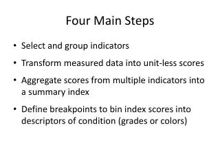
Main Steps of Beam Bending Analysis. Step 1 – Find Reactions at External Supports Free Body Diagram (FBD) of Entire Beam Equations of Force and Moment Equilibrium (3 in 2D) Step 2 – Shear and Bending Moment Diagrams Cutting Plane and FBD of Part of the Beam

E N D
Main Steps of Beam Bending Analysis • Step 1 – Find Reactions at External Supports • Free Body Diagram (FBD) of Entire Beam • Equations of Force and Moment Equilibrium (3 in 2D) • Step 2 – Shear and Bending Moment Diagrams • Cutting Plane and FBD of Part of the Beam • Use Equilibrium Eqs. to Express Internal Forces in Terms of Position Variable, “x” • Step 3 – Stress Distributions at Critical Sections • Linear Distribution of Bending (Normal) Stresses • Transverse Shear Stress Distribution in Terms of “Area Moment”
Summary of Stress Analysis Procedure in Symmetrical Beams • Find Centroid of Crosss-Section Neutral Axis (Table 4.2) • Choose x-y-z Ref. System Centered at Centroid • Normal Bending Stress • Zero at neutral axis • Max. at top and/or bottom surface • Transverse Shear Stress • Zero at top and bottom edge • Max. at neutral axis unless cross-section is narrower elsewhere • Z(y=y1)=width of cross-section where shear stress is calculated yA = Moment of area above y=y1 with respect to neutral axis
Solution of Example Problem 4.3 • Step 1 –Construct shear&moment diagrams • Step 2 –Find dmin=0.90in to resist allowable=35,000psi at section where Mmax=2500in-lb • Step 3 –Find dmin=0.56in to resist allowable=20,200psi for maximum direct average shear stress • Step 4 –Find dmin=0.65in to resist allowable=20,000psi for maximum transverse shear stress
TORSIONAL SHEAR • Circular Cross-sections (Fig. 4.7) • Cross-sectional planes remain plane and parallel if shaft is straight, torque about longitudinal axis, etc. • Maximum shear stress is always at the outer fibers • Relationships between power, speed, torque of rotating shaft, based on fact that 1 hp=33,000ft-lb/min, and 1 kw = 60,000N-m/min: hp=(Tn)/63,025, or kw=(Tn)/9549, where n=shaft speed in rev/min, T =torque in in-lb or Newton-meter • Noncircular Cross-sections: Complex solutions because of “warping” of cross-sectional surfaces (Fig. 4.8)
MEMBRANE ANALOGY for Torsion Analysis of Noncircular Bars • Based on similar governing differential equations and boundary conditions for: • the contoured deflection surface of a pressurized membrane and the • distribution of torsional shearing stresses in a twisted bar • Analytically and Experimentally Verified Observations: • Tangent to contour line coincides with direction of torsional shear at the corresponding point of cross-section • Max. slope of membrane at any point is proportional to corresponding magnitude of shear stress • Volume enclosed by datum base-plane and contoured surface is proportional to the torque applied on the twisted bar • Critical points of maximum shear identified by visualizing deformed membrane (Fig. 4.9)
Bending of Usymmetric BeamsShear Center • Torsion occurs if the plane of applied transverse force is not a plane of symmetry • Shear Center (Center of Twist) of Cross-Section • No torsion if plane of transverse forces passes through it • If one axis of symmetry, it lies on it, but not at centroid • If two axes of symmetry, it lies at their intersection point • If there is a point of symmetry, it lies at the centroid • See Table 4.5 for Shear Center location in cross-sections
MAE 343-Intermediate Mechanics of Materials Homework No.3 - Thursday, Sep. 9, 2004 • Textbook problems required on Thursday, Sep. 16, 2004: • Problems 4.17 and 4.19 • Textbook problems recommended for practice before Sep. 16, 2004: • Problems 4.16, 4.18 and 4.20