Download
1 / 19
190 likes | 328 Views
Outline 680XX Family Hardware Interfaces 68000 Hardware Interface Goal Understand 680XX hardware interfaces Learn how to attach memory, peripherals to CPU Reading Microprocessor Systems Design, Clements, Ch. 4. 680XX Hardware Interface. 68000 asynchronous interface

E N D
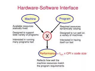
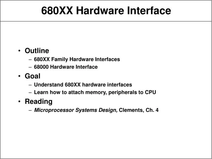
Outline 680XX Family Hardware Interfaces 68000 Hardware Interface Goal Understand 680XX hardware interfaces Learn how to attach memory, peripherals to CPU Reading Microprocessor Systems Design, Clements, Ch. 4 680XX Hardware Interface
68000 asynchronous interface request/acknowledge sequencing, no clock 24-bit address, 16-bit data handles bus arbitration 68020 asynchronous 32-bit address, 32-bit data dynamic bus sizing 68030 68020 plus synchronous mode burst-mode to fill cache 68040 fully synchronous external arbitration 680XX Family Hardware Interfaces
Figure 4.1 in text 64-pin package system support pins power, clock, reset, etc. memory and peripheral interface pins data I/O special-purpose pins interrupt management and bus arbitration Table 4.1 in textbook Signal conventions asserted - signal is in active state negated - signal is in inactive state asterisk suffix - active-low - active when at electrically low state, i.e. at ground example - RESET* 68000 Hardware Interface
Power supply 2 Vcc (+5V) pins 2 Gnd (0V) pins many more today - 100+ Vdd/Gnd pins in Alpha Clock input pin single-phase TTL-compatible signal used to derive all internal 68000 timing maximum speed - due to logic delays minimum speed - due to dynamic logic memory access is called a bus cycle 4+ clock cycles instruction is 1+ bus cycles System Support Pins
RESET* active low input/output open drain - external resistor to pull up can form wired OR with several input signals input - force 68000 to known state loads supervisor SP from $00000000 loads PC from $00000004 must be asserted with HALT* for 100 ms at power-up wait for startup of internal power supplies asserted for 10+ clock cycles otherwise output - resets external devices hooked to RESET* RESET instruction asserts RESET* for 124 clock cycles does not reset CPU System Support Pins (cont.)
HALT* active low open drain input/output input - halt processor at end of current bus cycle negate all control signals tristate (float) address and data buses function codes still active use to single-step bus cycles negate just long enough to permit bus cycle to execute in simple systems HALT* and RESET* are wired together can also be used to repeat bus cycle on memory error output - fatal error, CPU halts, asserts HALT* double bus error - processor is lost System Support Pins (cont.)
Memory-mapped I/O peripherals hooked on memory bus, look like memory Address bus A01-A23 - address 223 16-bit words specify read/write location tristate output pins - someone else can put address on bus during interrupt acknowledge A01-A03 indicate interrupt level being serviced A04-A23 set to ones used for vectored interrupt - peripheral will supply exception vector to locate handling routine Memory/Peripheral Pins
Data Bus D00-D15 tristate I/O pins transfer data to/from memory and peripherals word operation - all lines active byte operation - only data lines of byte being accessed active vectored interrupt peripheral puts interrupt vector number of D00-D07 AS* address strobe active low indicates contents of address bus are valid Memory/Peripheral Pins (cont.)
R/~W read/~write, specifies nature of bus cycle tristate output R/~W=1 - CPU not writing memory (reading or idle) R/~W=0 - CPU writing to memory floats when CPU gives up memory bus designer must use resistor to pull up to logical one make sure memory does not accidentally get written UDS* and LDS* upper and lower data strobes active low tristate outputs specifies which or both data bus bytes are being read/written control memory read and write select logic Memory/Peripheral Pins (cont.)
DTACK* data transfer acknowledge active low input indicates data on data bus is valid CPU waits until DTACK* is asserted wait states - idle clock cycles CPU reads data and then proceeds to next bus cycle generated via CPU read request, possibly delayed by timer Memory/Peripheral Pins (cont.)
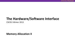
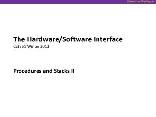
Bus error control BERR* - active low input error in current bus cycle detected by external logic - e.g. nonexistent physical address repeat bus cycle or take exception Bus arbitration control CPU, DMA controllers, or other CPUs could be bus master arbitration - decide who gets bus next when simultaneous requests BR* - bus request active low open drain input - can wire OR to all devices asserted by another device that wants to be bus master BG* - bus grant, active low output current master will release control at end of current bus cycle requestor can negate its BR* output BGACK* - bus grant acknowledge input requestor asserts when it sees BG*, is now bus master Special Function Pins
Bus Arbitration Signal Flow Current Bus Master I want bus Potential Bus Master BR* BR* You can have it BG* BG* I have bus BGACK* BGACK* ...
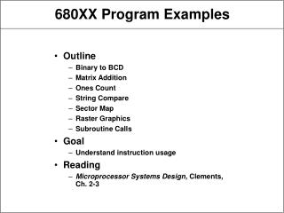
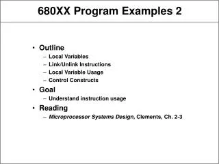
Function code outputs FC0-FC2 tristate outputs specify type of current bus cycle FC2 - user or supervisor mode valid half cycle before address bus provided primitive memory protection use MMU instead today mainly use for interrupt acknowledge Interrupt control interface IPL0*-IPL2* - interrupt request level inputs - 0 to 7 0 - no interrupt 7 - highest priority serviced if higher than interrupt mask in SR level 7 always serviced use priority encoder to combine 7 lines to 3 Special Function Pins (cont.) FC2 FC1 FC0 Cycle Type 0 0 1 User data 0 1 0 User program 1 0 1 Supervisor data 1 1 0 Supervisor prog 1 1 1 Interrupt ack
Interrupt Req/Ack Encoding VDD 68000 74LS148 Priority Encoder IRQ1* IRQ2* IRQ3* IRQ4* IRQ5* IRQ6* IRQ7* IPL0* IPL1* IPL2* A B C 74LS138 Priority Decoder IPL0* Y1 Y2 Y3 Y4 Y5 Y6 Y7 IACK1* IACK2* IACK3* IACK4* IACK5* IACK6* IACK7* IPL1* IPL2* FC0 FC1 FC2 E
Use to interface with 8-bit 6800 synchronous peripherals Motorola did not need to develop new family of peripherals VPA* active low valid peripheral address input indicates synchronous peripheral being accessed VMA* active low valid memory address output indicates valid address on address bus in response to VPA* E enable output timing signal used by 6800 peripherals CPU clock divided by 10 low for 6 cycles, high for 4 Synchronous Bus Control
Synchronous Data Transfer E Clock Address Address Valid Data Data valid tsetup thold
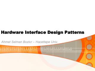
Fully interlocked handshake request, acknowledge, remove request, remove acknowledge Figure 4.11 Example CPU generates valid data at A CPU asserts address strobe at B memory detects strobe, places data on data bus, which is valid at C memory asserts data acknowledge at D CPU detects ack, reads data, negates address strobe at E memory negates data acknowledge at F Asynchronous Bus Control
Asynchronous Data Transfer A Address (fromCPU) Address Valid B E Address Strobe (from CPU) C Data (from Mem) Data valid D F Data Ack (from Mem) Signals shown as active high