Download
1 / 28
280 likes | 375 Views
AVL System for Fire Brigades. Technical solution presentation. AVL System for Fire Brigade. Principles Architecture Components Features Configuration. Principles. EADS TETRA system. AVL Client Applications. Location Server. Location. Requests. Principles (1/5).

E N D
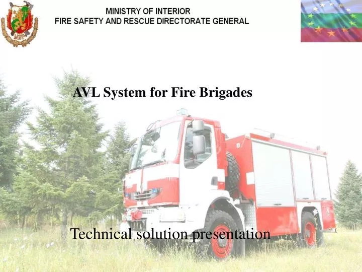
AVL System for Fire Brigades Technical solution presentation
AVL System for Fire Brigade. • Principles • Architecture • Components • Features • Configuration
EADS TETRA system AVL Client Applications Location Server Location Requests Principles (1/5) • Automatic Vehicle Location (AVL) • Provides the position of selected units in real time • Adaptive position updates based on moved distance or time interval • Geographical Information System (GIS) at Command and Control room and/or at the vehicles
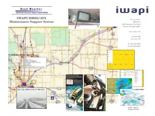
Resource DB 5. Typical AVL client applications in the control rooms and offices 6. Business critical database access 4. Location server 1. AVL applications in the vehicles 2. Radio terminals with GPS receiver 3. Radio Network Principles (2/5) Typical AVL Solution Our focus
AVL support in the radio network Principles (3/5) • Radio network • Efficient mechanisms to control load of the AVL updates and other data messages • An Application Programming Interface (API) for Location Server and other applications • Location server • Decodes LIP format location updates • Collects and stores the latest position data of the traced radio terminals in the network • Provides interface for the authorized AVL client applications to access location information of the radio terminals based on the definitions in the network • Manages the parameters of position updates for each organization TCS Server (3 pcs) interface 4. Location server 3. Radio Network
Principles (4/5) interface • AVL Client Applications in Control Rooms and Offices 5. Typical AVL client applications in the control rooms and offices • AVL client applications • Show real time location of the field forces on top of the map on screen • The resolution of the provided digital map is 1:100 000 • The resolution of the layer is 1:5 000 for 28 Regional Centers • The interface enables • easy integration of customized AVL applications • multi-vendor market for the AVL applications • time and changed position based as well as immediate location requests • one logical address to access for any subscribers’ location data
Principles (5/5) • Centralized AVL topology IP network Location Server A large TETRA network with several DXT switches Typical AVL client applications in the control rooms and offices • One Location Server / TETRA network • The centralized Location Server provides location and tracking data of all subscribers in the network for large number of the AVL Client Applications • Location Server collects location data through the distributed TCS Servers
Architecture (1/2) • AVL system architecture & data flows The configuration is a mono-site AVL server configuration with redundant server and database, associated to a web-based AVL Display composed of an AVL Display server and several Display clients. AVL server is connected to 3 TCS Servers: a primary cluster of 2 TCS on DXT1 and a secondary TCS on DXT2.
Architecture (2/2) • Fire Brigade Main Sites • Requirements on Data flows between : > TCS AVL Server > AVL Server AVL Display server > AVL Display Server AVL Display Clients
Components (1/3) • The AVL sub-system is composed of : • 1 AVL Server Cluster
Components (2/3) • 1 AVL Display Cluster
Components (3/3) • 29 AVL Clients • Dual screen web-based light clients • 1 with two 57" TFT LCD monitors • 28 with two 21" TFT LCD monitors
Features (1/5) • Resource management : • AVL operator manages resources • Units (HH or Vehicles) • Fleet (based on TETRA Organisation blocks and sub-blocks) • Flexible management of access rights • From Administration / Supervision level of AVL Display Server • From TETRA network (Organisation level) • Customisation of application via profiles saving : • map views • tracked units
Features (2/5) Map view • Tracked resources are identified (icon / name) • Operational status displayed through a colour code • Clicking on a tracked unit, the operator can : • Command the configuration parameters for tracking the resource (Maximum reporting interval, Maximum distance interval) • Get radio state of the resource • Change manually the operational status of the resource • Access to instant Replay • Open a new map view or modify the current map view which will be centred on this resource • Get the configuration data of this resource
Features (3/5) • Selection of different kind of maps (raster, vector, satellites). • Map layers are switched on or off automatically on basis of zoom level. • The AVL application allows to define some specific layers (Points of Interest such as hydrants or incident address).
Features (4/5) • List view • Operator has the possibility to focus on a set of resources in a permanent or temporary list :
Features (5/5) • Geo-fencing • Operator has the possibility, for each resource, to draw restriction zones Alarms are generated in case of violation of exclusion or inclusion rules
Hostname Subnet IP address Netmask Gateway DNS1 DNS2 Configuration (1/5) • IP Addressing plan • DXT sites • Sofia • OMU Subnet • SIPU Subnet • Burgas • TCS Subnet • AVL Server / AVL Display Server site • AVL Clients sites
Configuration (3/5) • TETRA BACKBONE Dimensioning : • The following figures give an estimate of dataflow related to AVL service, assuming 1000 Radio terminal with activated location feature registered in the network and a polling period of 90 seconds, (I.e.: 11 locations per second.) Sofia Burgas
Configuration (4/5) • IP Backbone dimensioning • IP traffic between TCS server and AVL server • IP traffic between AVL server and AVL Display server • IP traffic between AVL Display server and AVL Display clients
Configuration (5/5) • Users access rights management Fire Brigade 1 2 3 1.1 1.2 1.2.1 1.2.2 1.2.3