Download
1 / 18
190 likes | 376 Views
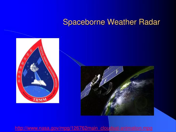
Spaceborne Weather Radar. http://www.nasa.gov/mpg/126762main_cloudsat-animation.mpg. Spaceborne weather radars have only been operational since 1997, however the idea has been around since the early 1960’s.

E N D
Spaceborne Weather Radar http://www.nasa.gov/mpg/126762main_cloudsat-animation.mpg
Spaceborne weather radars have only been operational since 1997, however the idea has been around since the early 1960’s. • Technological advances in signal processing, power requirements, and antenna design brought the cost to feasible levels during the 1990s. • This, along with increased awareness for the importance of quality rainfall measurements for climate applications, led the impetus for the design and launch of the Tropical Rainfall Measuring Mission and its precipitation radar (PR) in 1997, which is a Ku-band (frequency = 14 GHz, wavelength = 2.2 cm) scanning radar. • Now, CloudSat is the first spaceborne cloud radar, which will allow the mapping of clouds and light precipitation beyond the capabilities of TRMM. CloudSat is a W-Band (frequency = 95 GHz, wavelength = 3 mm) nadir pointing system. • The planned Global Precipitation Mission dual-wavelength precipitation radar (DPR), planned for launch in 2011, will have two frequencies at Ku (same frequency as TRMM) and Ka (frequency = 35 GHz, wavelength = 8.5 mm), which will allow retrieval of the drop size distribution through dual-wavelength techniques, will have higher sensitivity at Ku band. This will allow improved rainfall retrievals.
Comparison with ground-based radar • Same principle, less infrastructure • In low earth orbit, so 350 (TRMM)-750 km (CloudSat) Spaceborne radar generally has: • Lower transmit power • Lower sensitivity • Lower azimuthal resolution, higher vertical resolution • No Doppler or Polarimetric Capability (yet) • Moving at 10s of km/s, so only get snapshots of precipitation (vs. volume scans) • Cross-track scanning, or nadir (straight down) pointing angles
Spaceborne radar design considerations • There are many more careful engineering considerations and trade-offs when designing a spaceborne radar system compared with a ground-based system • Ideally, one would like to have high spatial resolution, good sensitivity, large coverage area (swath), little attenuation and a wavelength sensitive to the parameter of interest without being susceptible to Mie effects • These issues include: • Duty-cycle of scanning antenna vs. wide swath • Power available aboard spacecraft • Signal processing and data communications • Size and weight vs. wavelength, spatial resolution, sensitivity, beam filling, swath width, and sidelobes • Movement of satellite during pulse volume (satellite speed ~ 10 km s-1)
Design considerations The minimum detectable reflectivity is determined according to the radar equation: ; Where: Pr is the return power Pt is the transmit power C is the radar constant r is range G is the antenna gain Z is the equivalent radar reflectivity factor
For a spaceborne radar, the transmit power, wavelength, and antenna gain are limited by the size of the antenna (3 m), power available (from solar panels), receiver sensitivity, and range from the ground (750 km) • These factors limit the minimum detectable reflectivity of the TRMM radar to 17-18 dBZ
The “fraction of the beam filled”, plotted as F in this diagram, shows that at an incidence angle (q=30º), the amount of beam filling is strongly determined by the radar’s beam width. Iguchi and Meneghini (1990)
Partial Beam Filling Often times, the radar suffers from “partial beam filling” either by precipitation or by the surface clutter. This introduces a non-linear averaging problem because the power returned is partitioned in an unknown fashion.
The surface return is both a blessing and a curse for spaceborne radar. • It can be used as a reference for attenuation correction and calibration, since it is a stable quantity that can be compared over time and space • Its reliability is good apart from at high incidence angles with high wind speed) over ocean • Over land its standard deviation is generally larger than over ocean • It also introduces non-precipitating echo, which increases in depth away from nadir in the main lobe of the radar, as well as sidelobes (which are lower in returned power, but are higher in altitude
Good range resolution is required to optimize vertical resolution for scans away from nadir - must weigh against number of samples at each gate. Iguchi and Meneghini (1990)
Sidelobes are a problem because ground return is so intense. These plots show the ratio of the rain to surface return as a function of rain rate and altitude. Iguchi and Meneghini (1990)
The surface return masks out rain return near the surface due to the main lobe and side lobe clutter. Here are results from two incidence angles: 10° (left) and 30° (right) for 4 different rain rates. Iguchi and Meneghini (1990)
Sidelobes and Surface Effects Hanado and Ihura (1992)
Sidelobe illustration - the serial sidelobes appear to radiate up from the nadir point due to the increasing inclination angle. Hanado and Ihura (1992)
Mirror Image: Power making 4 hops back to the receiver Schematic diagram of the mirror image Mirror return TRMM PR observed rainfall reflectivity cross section Courtesy K. Nakamura