Download
1 / 25
250 likes | 479 Views
EEE 352: Lecture 40. http://www.eas.asu.edu/~ferry/ECE352.htm. High Electron-Mobility Field Effect Transistors (HEMT) * Three terminal devices * Depletion Mode Device (Like the MESFET) * Behavior like the MOSFET * Field effect action Threshold voltage Current saturation.

E N D
EEE 352: Lecture 40 http://www.eas.asu.edu/~ferry/ECE352.htm High Electron-Mobility Field Effect Transistors (HEMT) * Three terminal devices * Depletion Mode Device (Like the MESFET) * Behavior like the MOSFET * Field effect action Threshold voltage Current saturation
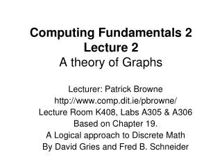
Lattice constant versus band gap of the most important III-V compound semiconductors
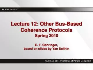
Conduction band diagram of a delta doped HEMT. The Fermi level EF and the quantum energy level Ee of the electrons in the channel are indicated by the dashed line.
ionized donors electron inversion layer Ec Ev p-type GaAs semiconductor metal n-type AlGaAs The HEMT Device When the semiconductor is connected to the metal by a “back contact”, the Fermi levels align (no charge in the interface). In MESFETs, the interface charge dominated the zero bias condition; Here, the heterojunction interface is GOOD—very small interface charge levels. The GaAsAs surface is dominated by these states, but this is a metal-Gate Inversion layer is created at the interface between GaAs and AlGaAs, just as in the MOSFET, but here it occurs due to the donors in the AlGaAs. Acts like “oxide”
ionized donors electron inversion layer Ec Ev p-type GaAs semiconductor metal n-type AlGaAs The Schottky barrier causes depletion of the donors near the surface. The conduction band offset at the heterojunction causes the donors to be ionized—the electrons move into the potential well. If this region exists, it is BAD. The gate has no control over the charge in the channel. The two depletion regions must merge in the center.
CONTROL GATE SOURCE DRAIN GaAlAs Layer n n GaAs LAYER The HEMT Device n-type contacts are created in the p-type substrate. The n-type channel is INDUCED by the DONORS, and connects these two contacts. The number of electrons in the CHANNEL is determined by the GATE, so the CONDUCTANCE is modulated by the GATE. The AlGaAs layer acts much like the oxide in the MOSFET. The difference, however, is that the HEMT is a DEPLETION device, and VG < 0, as in the MESFET.
fm DEc DEc Field Effect Action ionized donors Ec fm Ed metal Quantum well vanishes; no carriers are present at the interface. Ec
fm DEc At sufficiently negative bias, the quantum well vanishes, and there is not charge at the interface. This is the “threshold” or “turn-on” or “pinch-off” voltage. metal EFm Ec EFs The threshold voltage is defined here as a negative quantity. The gate bias gives the difference between the two Fermi levels.
fm DEc For a more positive gate voltage, the quantum well begins to fill with carriers. metal EFm Ec EFs
fm DEc For still smaller values of the negative gate voltage (more movement toward positive bias), the density in the inversion layer increases. metal EFm Ec EFs As long as this minimum in potential stays away from the Fermi level in the semiconductor, the donors will remain ionized.
DEc ionized donors Ec fm EFm EFs Ed If the donor level in the AlGaAs approaches the Fermi level in the semiconductor, these donors will start to neutralize, and the gate loses control—BAD. If the gate voltage goes positive, the Schottky diode becomes forward biased, and conducts current—BAD.
BIASED GATE DRAIN AlGaAs Layer SOURCE - - - - - - - - - - n+ n+ CHANNEL P-TYPE Field Effect Action • As we progressively NEGATIVELY bias the gate we DEPLETE the inversion regions, and a THRESHOLD VOLTAGEVT is finally reached where the continuous electron CHANNEL between the contacts vanishes. VGS<0 VDS In the CHANNEL, the voltage is a fraction of the DRAIN voltage VDS. This is written as V(y). At any position, the sheet density ns is written as http://www.ifh.ee.ethz.ch/Microwave/InP/research.html#plasma http://www.mc2.chalmers.se/mc2/mel/res/wbg/gan_hemt.xml
BIASED GATE DRAIN AlGaAs Layer SOURCE - - - - - - - - - - n+ n+ CHANNEL P-TYPE Field Effect Transistor Action VGS<0 VDS Then: This is a simple approximation, that V(y) is a function of y alone—we are ignoring two-dimensional effects.
BIASED GATE DRAIN AlGaAs layer SOURCE - - - - - - - - - - n+ n+ CHANNEL P-TYPE Field Effect Transistor Action VGS<0 VDS
DRAIN CURRENT INCREASINGPOSITIVEGATE BIAS CHANNELPINCH-OFF SOURCE-DRAIN VOLTAGE Field Effect Action • The variation of source drain current with voltage is more COMPLEX than expected. • The conductance DOES increase as gate voltage becomes more positive Note how the slope of the ID-VD curves INCREASES with VG • A region of SATURATED CURRENT is observed. Current SATURATES when Zero current when
DRAIN CURRENT INCREASINGNEGATIVE GATE BIAS AlGaAs Layer CHANNELPINCH-OFF SOURCE-DRAIN VOLTAGE Field Effect Action • Saturation results from the elimination of the INVERSION REGION around the drain. • In the saturated region, increasing source-drain voltage has TWO effects: It tries to INCREASE current in accordance with Ohms law, But the conductance DECREASES as the depletion grows. • In the saturated regime these two COMPETING effects CANCEL BIASED GATE SOURCE DRAIN - - - - - - - - - - n+ n+ CHANNEL P-TYPE Pinch-off point moves to left as VDS exceeds the value needed to saturate the current. Channel electrons are injected into pinched off (p-type depleted) region and DIFFUSE to drain. Current is set by ACTIVE CHANNEL.
DRAIN CURRENT BIASED GATE DRAIN AlGaAs Layer SOURCE INCREASINGNEGATIVEGATE BIAS - - - - - - - - CHANNELPINCH-OFF n+ n+ CHANNEL SOURCE-DRAIN VOLTAGE P-TYPE Field Effect Transistor Action VGS<0 VDS n-type contacts are created in the substrate. The n-type channel is INDUCED by the DONORS in AlGaAs, and connects these two contacts. The number of electrons in the CHANNEL is reduced by the GATE, so the CONDUCTANCE is modulated by the GATE.
Drain also has multiple fingers to carry more current. Source is at ground potential and is wrapped around in order to shield the output from the input. Connection to the actual source fingers is by an “airbridge” over the gate and dielectric. Gate electrode (multiple “fingers” are used to increase the so-called gate width in order to increase the current from the device. The actual gate fingers are covered with a dielectric. Power HEMT from TriQuint
HEMTs Multi-stage HEMT microwave amplifier A monolithic microwave integrated circuit