Download
1 / 65
750 likes | 1k Views
Shading, Surfaces & Textures. Outline. Polygon shading models Constant, interpolated, polygon mesh, Lambert, Gouraud, Phong Lighting models Lambert, Phong, Blinn Surfaces properties Surface mapping Texture Bump Displacement …. Lighting algorithms.

E N D
Outline • Polygon shading models • Constant, interpolated, polygon mesh, Lambert, Gouraud, Phong • Lighting models • Lambert, Phong, Blinn • Surfaces properties • Surface mapping • Texture • Bump • Displacement • …
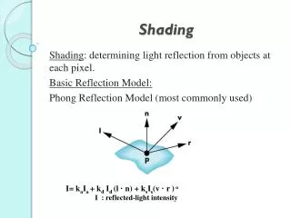
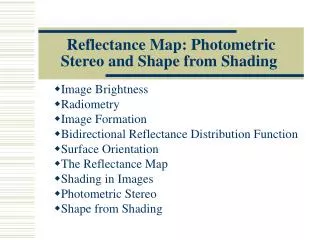
Lighting algorithms • Most algorithms use the polygon or surface normal (vector that is perpendicular to the polygon) • The amount of light reflected depends on the angle of the incident light, e.g. for diffuse reflection: N L
Constant shading • Also known as Lambert, faceted and flat shading • Calculates a single intensity value for each polygon • Valid if following assumptions are true: • Light source is at infinity (i.e. angle between light and surface is constant) • Viewer is at infinity (i.e. angle between viewer and surface is constant) • Polygon is not an approximation of a curved surface
Interpolated shading • Shading is linearly interpolated across polygon • Faster than calculating each pixel, better than flat shading • Still assumes that polygon represents the true surface
Polygon mesh shading • Many sets of polygons actually are approximations to curved surfaces • Shading the polygons to realistically simulate the surface is therefore important • Several methods exist toachieve this, the most important of which are Gouraud and Phong shading.
Gouraud shading (Henri Gouraud, PhD 1971) • This is a form of intensity interpolation shading • Starts from knowing the normal of the surface at each vertex of the polygon • These may be stored with the mesh or may be averaged from the adjacent polygons • Next step is to calculate the vertex intensities • This will use the vertex normal and the illumination algorithm
I2 IP I1 I3 Gouraud shading (2) • The polygon is then shaded by: • Interpolating the intensities along each edge • Interpolating across the polygon between the edges along each scan line
Gouraud algorithm • Compute SA, SB, SC for triangle ABC. • Si = shade of point i. • For a scanline XY, compute SX, SY by interpolating • e.g. tAB = |AX| / |AB|. • SA = tAB* SA + (1-tAB)*SB • Compute SP • By interpolating between SX and SY B X P Y scanline SX SP SY A C
Phong shading (Bui-Tong Phong, PhD 1975) • This is a form of normal-vector interpolation shading • Starts from the normal vector at each vertex again, but interpolates the vector rather than the intensity
Phong shading (2) • In general, this yields much more realistic results, especially for specular surfaces • Gouraud shading may miss specular highlights • It is several orders of magnitude slower than Gouraud
Problems with interpolated shading • Polygonal silhouette • Perspective distortion • Orientation dependence • Shared vertices • Unrepresentative vertex normals
Polygonal silhouette • Approximation is polygonal, so no matter how good the shading algorithm the silhouette will be faceted • Can be improved by increasing the polygon count at expense of processing time
Perspective distortion • Because the interpolation is based on the scan lines, the number of interpolation increments per polygon depends on the angle of the polygon to the viewer • Steep angle = few increments • Shallow angle = more increments
Orientation dependence • Because interpolation occurs between vertices and along scan lines, result depends on orientation of polygon relative to scan lines
Shared vertices • Problems occur when adjacent polygons do not share vertices • This can lead to discontinuities in shading
Unrepresentative vertexnormals • Vertices may not adequately represent the surface geometry • Usually can be solved by further subdividing surface
Surfaces • Definition of visual characteristics of a surface • Often defined by a ‘shader’ or ‘material’ • Specifies colour, how shiny it is, etc.
Surface parameters • Colour usually defined by RGB values or via GUI • Ambient is a false parameter that defines how ‘ambient’ light is treated • Diffuse parameter specifies how much light in total is evenly reflected • Specularity defines how shiny a surface is (a high value will have highlights like a billiard ball) • May also have controls for highlight size and colour
Advanced surface parameters • Reflectivity defines how much of the surrounding environment is reflected by the surface (like a mirror) • Transparency defines of the background is visible through the surface • Translucency defines how much light is transmitted through the surface • Refractivity defines how much light is bent as it enters and leaves the material
Surfaces in Maya • Basic materials: • Lambert • Phong • Phong E • Blinn • Special materials: • Anisotropic, Layered Shader, Ocean Shader, Ramp Shader, Shading Map, Surface Shader, Use Background
Lambert • This is the simplest material • It creates a matt surface with diffuse and ambient components but no highlights • The shading interpolates between adjacent polygon normals so the surface appears smooth • It uses Lambert’s cosine law
Lambert’s Cosine Law • “The reflected luminous intensity in any direction from a perfectly diffusing surface varies as the cosine of the angle between the direction of incident light and the normal vector of the surface” Johann Lambert, 1728-1777.
Lambert’s Cosine Law • Ideal diffuse surfaces obey this cosine law • Often called Lambertian surfaces. • Id = kd Iincidentcos = kd Iincident (N·L). where kd is the diffuse reflectanceof the material. • Wavelength dependent, so usually specified as a colour.
Phong (Bui-Tong Phong, 1975) • This lighting model includes specularity • This takes into account that the amount of light you see depends on the viewer’s angle to the surface as well as the light’s angle • His original formula for the specular term: • W(i)(cos s )n • s is the angle between the view and specular reflection directions. • “W(i) is a function which gives the ratio of the specular reflected light and the incident light as a function of the the incident angle i.” • Ranges from 10 to 80 percent. • “n is a power which models the specular reflected light for each material.” • Ranges from 1 to 10.
L N R V Phong lighting model • More recent formulations are slightly different • Replace W(i) with a constant ks, independent of the incident direction • Is= ks Iincidentcosn = ks Iincident (V·R)n. • V is the view direction. • R is the specular reflection direction
Maya’s ‘Phong E’ • Uses a simplified model, faster to render than pure Phong
Maya’s Blinn (Jim Blinn, 1977) • Based on Blinn-Phong shading (an adaptation of Phong) • Offers great control over specularity but in general will not look as ‘shiny’ as a Phong material
2D texture mapping • A ‘cheap’ way of enhancing the the surface definition • So far, surfaces have been defined with a plain colour • In real life, many surfaces are multi-coloured • E.g. Wood looks ‘wooden’ because of many different colour variations in the grain
2D texture mapping (2) • 2D texture mapping involves applying a 2D image to the surface of a 3D object • In this case the term ‘texture’ applies to the image rather than the more traditional ‘feel’ of the surface • Textures may be ‘real’ (e.g. scanned), manually generated (e.g. with a paint program) or procedurally generated (e.g. by a computer program)
2D texture mapping (3) • The process of applying the texture is the ‘mapping’ • The two mapping processes: • Projecting the image onto the surface • Stretching the image to fit on the surface
Projection mapping • In projection mapping the image is projected through space • Wherever it ‘hits’ the surface the surface becomes the colour of the texture • The purest form of this is planar projection
Cylindrical projection • Image is bent into a cylinder before projection takes place • Object is then placed ‘in’ the cylinder
Spherical projection • Image bent onto an imaginary sphere before projection • Object placed ‘in’ sphere
Limitations • Unless mapping on a perfect flat surface, cylinder or sphere, all projection methods will have a tendency to ‘streak’ • Parameterised texture mapping offers a solution to this problem
Parameterised (UV) mapping • Imagine printing the texture image onto thin transparent film • Then stretch the film over the surface • This is the principle of parameterised texture mapping
Parameterised mapping (2) • The 2D texture image is (obviously) an array of rectangular pixels • These can be referenced by Cartesian coordinates, usually with the lower left pixel being (0,0) (and for a 512 x 512 image the top right being (511,511)) • Each pixel rectangle is then mapped to a corresponding area of the 3D surface
Parameterised mapping (3) • You therefore have to divide the surface into the same number of steps • The surface patch is defined to use the coordinate system U and V to specify locations on it • The area defined by (0,0) on the surface has the colour applied to it from the image pixel at (0,0)
Procedural textures • Textures can be generated by procedures rather than using predefined images • This is good for regular patterns (e.g. brickwork) or (semi-)random patterns (e.g. noise)