Download
1 / 57
570 likes | 712 Views
Mn/DOT Combined Smoothness Specification Operator Certification Training Workshop July 12, 2010. Combined Smoothness Spec. What’s Different? Smoothness evaluation Areas of localized roughness (ALR) Profile Viewing and Analysis (ProVAL) software

E N D
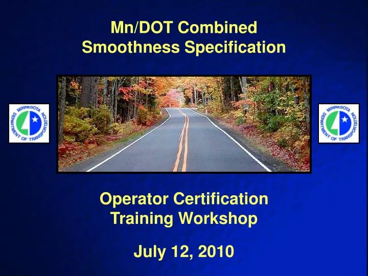
Mn/DOT Combined Smoothness Specification Operator Certification Training Workshop July 12, 2010
Combined Smoothness Spec. • What’s Different? • Smoothness evaluation • Areas of localized roughness (ALR) • Profile Viewing and Analysis (ProVAL) software • Profile Summary worksheets • Operator certification
1. Smoothness Evaluation • Both the right and left wheel paths must be profiled with a certified Inertial Profiler. • After corrective work, an IRI value will be computed for each wheel path, for each 528-foot segment, and then averaged. This average IRI value will used to calculate the segment pay adjustment. • IRI values will be determined with ProVAL’s “Ride Quality: Fixed Interval.” • Exclusion: paving with posted speeds < 45 mph
2. Areas of Localized Roughness • Will replace bumps/dips • 25-foot continuous IRI that exceeds 125.0 inches/mile • Will be analyzed in the right wheel path only • ALR and grinding locations will be determined by ProVAL’s “Smoothness Assurance.”
2. Areas of Localized Roughness • ALR that exist after paving will require corrective work. • ALR that remain after corrective work will be assessed a deduction of either $5.00 per linear foot or $10.00 per linear foot, depending on the magnitude of roughness. • Exclusion: paving with posted speeds < 30 mph
Required Data by Posted Speed • 1. Posted Speed ≥ 45 mph • Smoothness (both wheel paths) • ALR (right wheel path only) • 10-foot straightedge • 2. 30 mph ≤ Posted Speed < 45 mph • ALR (right wheel path only) • 10-foot straightedge • 3. Posted Speed < 30 mph • 10-foot straightedge
ALR > Bumps/Dips • Areas of localized roughness are generated from IRI, an index that measures what passengers actually feel. • Accurate identification of bumps/dips is hindered by the design of the California Profilograph. • The California Profilograph ignores or minimizes some bumps/dips, while exaggerating or manufacturing others.
Because its front and rear wheels are in contact with the pavement surface, the profilograph cannot accurately measure the pavement profile. Design Limitations of Profilograph
Actual Profile Dip Profilograph Trace Dip Phantom Bumps Do These Bumps Really Exist?
25-foot sliding window Applying a 25-foot Moving Average
125 feet 54 in/mi Continuous IRI: 25-foot Intervals
Areas of Localized Roughness 125 in/mi Areas of Localized Roughness
3. ProVAL • Developed by the Transtec Group for the U.S. Federal Highway Administration (FHWA) and the Long Term Pavement Performance Program (LTPP) • Free to download at www.roadprofile.com • Contractor ERD values will be imported into ProVAL to calculate 528-foot IRI values, areas of localized roughness, and recommended grinding locations.
Ride Quality ALR
Ride Quality 528’ IRI Values
Exercise #1 • Let’s practice creating the first set of ProVAL reports that must be submitted to the Project Engineer: • Ride Statistics at Intervals (within 5 days of paving placement) • Smoothness Assurance Grinding (prior to corrective work) • Open ProVAL and load “Exercise1.erd.”
Smoothness Assurance Histograms Enter this value into Profile Summary’s 125 ≤ ALR < 150 box
Smoothness Assurance Histograms Enter this value into Profile Summary’s 150 ≤ ALR < 250 box
Exercise #2 • Let’s practice creating the final set of ProVAL reports that must be submitted to the Project Engineer: • Ride Statistics at Intervals (within 5 days of corrective work) • Smoothness Assurance ALR Histograms (within 5 days of corrective work) • Open ProVAL and load “Exercise2.erd.”
Editor Enter this value into Profile Summary’s 150 ≤ ALR < 250 box
Exercise #3 • Let’s practice using ProVAL’s Editor to create two subsections: • 1,000 feet to 3,000 feet • 3,500 feet to 5,500 feet • After creating the new sections, let’s compare their respective IRI values. • Open ProVAL and load “Exercise3.erd.”
4. Profile Summary Worksheets • All green cells are to be filled in by contractor. • 528-foot IRI values must be entered for each wheel path. The average IRI will be calculated automatically by the worksheet. • ALR data should be entered only on the first Profile Summary for an ERD file.