Download
1 / 23
390 likes | 659 Views
Optical Alignment with Computer Generated Holograms. James H. Burge, Rene Zehnder, Chunyu Zhao College of Optical Sciences Steward Observatory University of Arizona. Computer Generated Holograms. Use diffraction to create a desired wavefront

E N D
Optical Alignment with Computer Generated Holograms James H. Burge, Rene Zehnder, Chunyu Zhao College of Optical Sciences Steward Observatory University of Arizona
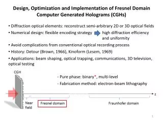
Computer Generated Holograms • Use diffraction to create a desired wavefront • Modern fabrication provides >100 mm patterns with <0.1 µm pixels. That’s > 1012 pixels! Incredible dynamic range
Accuracy and flexibility • CGHs transform wavefronts with very high accuracyErrors are typically < l/100 • Any wavefront shape can be created No special solution for spheres • Multiple wavefronts can be created from the same CGH • The registration between the different wavefronts is also very accurate
CGH for interferometric measurement of aspheric surfaces • Interferometers use light to measure to ~1 nm surface errors, for spherical or flat surfaces • CGH can change spherical wavefronts to aspheric, allowing the use of interferometers for measuring aspheric surfaces Aspheric surface to be measured aspherical wavefront Spherical wavefront Interferometer CGH
Alignment of CGH • Reflect wavefront back into the interferometer • Use this to align the CGH to the wavefront Spherical wavefront Interferometer Reflection CGH
CGH for aligning the aspheric mirror • Use numerous holograms on a single substrate to provide both wavefront and alignment information. • For alignment, the CGH can project bright crosshair patterns
CGH for testing off axis parabola A single substrate provides: - reference for interferometer - null lens for aspheric surface - creates 5 reference marks, 4 around edge, 1 on optical axis
CGH alignment of a 24-in off axis parabola(600-in ROC, 60 inches off axis) Phase map l/20 rms CGH null lens incorporates alignment marks Easily align axis to 0.020” by eye
Projection of fiducial marks • The positions of the crosshairs can be controlled to micron accuracy • The patterns are well defined and can be found using a CCD • Measured pattern at 15 meters from CGH. Central lobe is about 100 µm FWHM
Use of CGH for optical alignment Aligning the test for a 1.7-m off axis parabola 50 cm spherical mirror aligned within 7m CGH aligned within 7m 1.7m diameter OAP
Projecting alignment marks through other optics Aligning test for a 1.7-m off axis parabola Tilted spherical mirror • We need to place the OAP to the right place • Projecting a mark onto the OAP gives lateral position • Need a second mark to get the clocking right CGH Interferometer Relay Lens Clocking mark Positioning mark
Creating desired alignment features Aligning the OAP
Use of CGHs for optical alignment Aligning the Sphere to within 7m The position of the sphere is known if 3 points on its surface are known
Use of CGHs for optical alignment Aligning the Sphere to within 7m Placing a ball concentric to zero order gives a very good reference Distance betweenballs can be measuredwith metering rods Lateral position of the balldefined by lightAxial position defined bymetering rod CGH Attaching the mirror to three balls defines its positionThe fourth ball gives redundant information
Alignment of tooling balls to light created by CGH Use tooling balls because they provide good mechanical interface Beam with ball at focus well aligned Very sensitive to lateral motion of the ball but not for axial motion Misaligned ball cases return beam to shift
Ball alignment tool 1. Align a tool to the projected beam 2. Use the tool to laterally align the ball CCD Sensitivity comes from the geometry
Ball Alignment Tool CCD camera Ball at mirror Aperture Beam splitter Direction of the reference beam ~2 µm resolution
Use of CGHs for optical alignment Metering rods in action
Multiple patterns We use multiple patterns of the same substrate • Divide the regions on the CGH. Each has a single pattern • Derive a single pattern the gives simultaneous wavefronts
Single CGH with multiple references Position sensing detector CGH creating multiple wavefronts
Conclusion • CGHs are probably the most accurate and flexible things in optics • Whatever your problem is, you can probably solve it with a CGH.