Download
1 / 43
460 likes | 615 Views
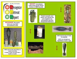
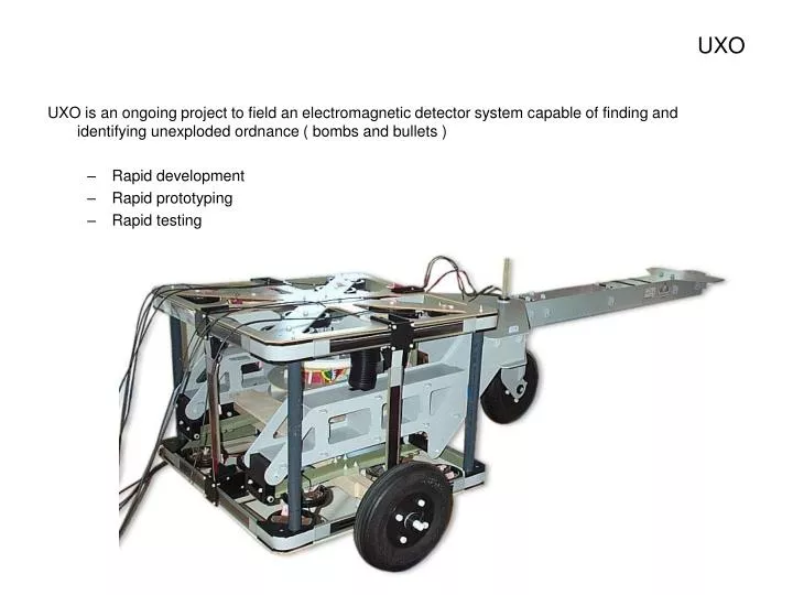
UXO. UXO is an ongoing project to field an electromagnetic detector system capable of finding and identifying unexploded ordnance ( bombs and bullets ) Rapid development Rapid prototyping Rapid testing. What we are looking for. General requirements / desirements.

E N D
UXO UXO is an ongoing project to field an electromagnetic detector system capable of finding and identifying unexploded ordnance ( bombs and bullets ) • Rapid development • Rapid prototyping • Rapid testing
General requirements / desirements This is the first prototype, the “Lawn Buggy” version. It’s purpose is to study how we have to handle this coil system to get the performance we need • Non-magnetic, non-metallic • Smooth ride • Damping is good, more is better.** • One-man operation, push or pull. • Fits through the laboratory door ! • Must have adjustability to accommodate real masses and observed sensitivity to disturbances.
Features • Non-magnetic construction; plywood, plastic, rubber, glue • Removable Boom • Solid tires (foam-filled) • Pneumatic tires (Add-on) • Fiberglass leaf springs • Pneumatic load levelers (Add-on) • Double sphere universal joint coil interface • Pneumatic Roll compensation and damping (Add-on) • Aggressive Pitch damping (Add-on) • More aggressive Roll compensation and damping. (Add-on) • Expected to have a short, useful life. Iterated quickly into obsolescence. • It fits through the Lab door.
Chassis Removable boom In “lab mode”, the boom can be removed and the tailwheel moved forward
The Chassis Wood and ply wood construction Waterjet profiles + ‘tab and slot’ structureallow fast turnaround
Suspension Plastic wheel assemblies. Both foam-filled and Pneumatic wheels are ready to go. Fiberglass leaf springs
Suspension Plastic wheel assemblies. Both foam-filled and Pneumatic wheels are ready to go. Fiberglass leaf springs Plywood and fiberglass axel assembly
Chassis The Base plate stiffens the structure
Chassis with coil frames The Base plate stiffens the structure But, must be installed inside the Coil frames
Coil support structure Outer sphere seat assy
Coil support structure Spherical bladder Outer sphere seat assy
Coil support structure Inner sphere plug assy Spherical bladder Outer sphere seat assy
Coil support structure Coil frame support structure Inner sphere plug assy Spherical bladder Outer sphere seat assy
Coil support structure Coil frame and Reciever mount plates
Coil support structure Recievers Coil frame and Reciever mount plates
Coil support structure Cross bracing (May not be needed ?)
Fully assembled test rig with electronics Laptop PC Battery Pack Readout electronics
Roll damping option This “bottle jack” assembly was designed to accommodate Coil mass exceeding the 100 lb design goal for the leaf springs. Plumbing options allow pneumatic tuning and damping over a useful range. The concept was bench tested, showed promise, and even led to some enthusiasm for active suspension. A simpler solution can be installed on the current prototype.
1-Meter Cross-Coil Prototype The mechanical design was driven by two primary requirements; to Improve the mechanical precision in the placement and alignment of the coil elements, and , to provide a robust, integrated instrument package appropriate for field testing. X coil pair Assembled instrument Z coil pair Receiver coil arrays Y coil pair
The 1-Meter Prototype currently under construction integrates precision winding forms and assembly features with structurally efficient panel assemblies Panel construction concept showing indexing features and assembly exploded view Coil form assembly prior to winding the transmitter coils. Coils are shown here as an example of the final coil location after assembly. The X and Y coils are actually wound onto the assembled cross panels as a sub-assembly Z transmitter coils and Receiver arrays are wound and assembled as separate panels..
Receiver panel The Receiver coils are wound on mandrels that become integrated into panels that includes electrostatic shielding. The transmitter coils are wound on machined coil forms as matched pairs. X and Y coils are wound in place on the assembled coil forms The panels are assembled into the instrument cube using indexing features machined to insure robust alignment and stability. Z transmitter panel X transmitter pair Wound as mirror-image duplicates Y transmitter pair Wound as mirror-image duplicates Z transmitter panel Receiver panel
Electrostatic shielding is integrated into each coil panel unit during panel fabrication. Core and skin materials are non-conductive and non-magnetic. Shields are etched copper on kapton and are applied to the panel skins. The final package is an integrated panel with the coil elements locked in their relative positions. Transmitter panels are assembled in similar fashion with the coils wound directly onto machined surfaces in the panel coil form. Skins and Core .005” thick shields on the outer panel skins Receiver coil on mandrel Cutaway view of a Receiver panel
The field test configuration features a light weight carriage assembly With provision for GPS antenna and calibration hardware. GPS antenna Receiver Plate Z-Transmitter plate X-Y Transmitter assembly Z-Transmitter plate Receiver plate
Here, the carriage assembly is shown without the detector coil. The GPS antenna is shown in it’s relative location. The Field-ready cart concept including bumpers, electronics and laptop computer. The electronics were later moved inside the beam structure. There is also a ‘tailwheel’ option not shown here
Proof-of-concept model parts have been cut by waterjet and are being dry-fitted into coil form sub assemblies. Here, the X and Y Transmitter assembly is being wound
The transmitter assembly is complete and is wired into the field electronics for check out and diagnostics Meanwhile, the Receiver panels are getting their last internal hookups before being laminated into structural panels. In this picture, the receiver coils are embeded in the foam panels. The shield circuitry is being completed. The next step willl be to add skins and laminate the assembly to become the receiver panel.
A word about the process….. Design around the Waterjet process allowed several huge advantages including speed, cost , and accuracy. It also allowed rapid iteration at modest cost. The simplicity is illustrated here. Pre-laminated composite panels are cut to precise profiles on the Waterjet. Parts are immediately available for dry-fit and tolerance checks. Assembly follows with parts snapped into place and epoxy bonded. No fixtures or tooling was used.
This lightweight box beam is typical of the cart and detector construction. In this picture, the beam is dry-fitted together (Without glue) and weighs ~27 lbs including the support assembly at the far end of the beam. The assembled cart, ready to receive the detector assembly. The detector support frame and wheel assembly are both height adjustable to set the ground clearance under the detector coils.